

*Optional flashing beacon (visual alarm).
**Optional visual and audible alarms.

Detects oil and indicates when the separator’s oil storage is full.
This probe is required in order for a treatment device to comply with BS EN 858.

Monitors the silt layer in the oil separator and indicates when the silt layer has reached its maximum level.
Indicates when the liquid level in the oil separator rises excessively e.g. in an outlet blockage situation.
| Alarm Type | Alarm Features | ||||||
|---|---|---|---|---|---|---|---|
| BMS | GSM (Text Message) | Max. Cable Length (M) | Probe Options | ||||
| Oil | Silt | High Level | |||||
| Oil | SPEL DY14400 Oil Alarm device | 200 | ✓ | ||||
| SPEL OMS-1 Oil Alarm device package for oil separator* | * | 100 | ✓ | ||||
| SPEL OISET-1000 Alarm device package for oil separator | ✓ | 300 | ✓ | ||||
| High Level | SPEL idSet-34 LIQ high level | ✓ | 300 | ✓ | |||
| SPEL idOil-30 LIQ high level | ✓ | 300 | ✓ | ||||
| SPEL idOil-30 3G LIQ | ✓ | ✓ | 300 | ✓ | |||
| Oil | SPEL idSet-34 OIL Oil | ✓ | 300 | ✓ | |||
| SPEL idOil-30 OIL Oil | ✓ | 300 | ✓ | ||||
| SPEL idOil-30 3G OIL Oil | ✓ | ✓ | 300 | ✓ | |||
| Silt | SPEL idSet-34 SLU Silt | ✓ | 300 | ✓ | |||
| SPEL idOil-30 SLU Silt | ✓ | 300 | ✓ | ||||
| SPEL idOil-30 3G SLU Silt | ✓ | ✓ | 300 | ✓ | |||
| High Level/Oil | SPEL idSet-34 LO High level/Oil | ✓ | 300 | ✓ | ✓ | ||
| SPEL idOil-30 LO High level/Oil | ✓ | 300 | ✓ | ✓ | |||
| SPEL idOil-30 3G LO High level/Oil | ✓ | ✓ | 300 | ✓ | ✓ | ||
| Oil/Silt | SPEL idSet-34 OS Oil/Silt | ✓ | 300 | ✓ | ✓ | ||
| SPEL idOil-30 OS Oil/Silt | ✓ | 300 | ✓ | ✓ | |||
| SPEL idOil-30 3G OS Oil/Silt | ✓ | ✓ | 300 | ✓ | ✓ | ||
| High Level/Silt | SPEL idSet-34 LS High level/Silt | ✓ | 300 | ✓ | ✓ | ||
| SPEL idOil-30 LS High level/Silt | ✓ | 300 | ✓ | ✓ | |||
| SPEL idOil-30 3G High level/Silt | ✓ | ✓ | 300 | ✓ | ✓ | ||
| High Level/Oil/Silt | SPEL idSet-34 LOS High level/Oil/Silt | ✓ | 300 | ✓ | ✓ | ✓ | |
| SPEL idOil-30 LOS High level/Oil/Silt | ✓ | 300 | ✓ | ✓ | ✓ | ||
| SPEL idOil-30 3G LOS High level/Oil/Silt | ✓ | ✓ | 300 | ✓ | ✓ | ✓ | |
Ideal for new build sites or where mains supply is readily available, making installation efficient and cost effective. The unit has an audible alarm and mute button. there is provision for a remote low power beacon.
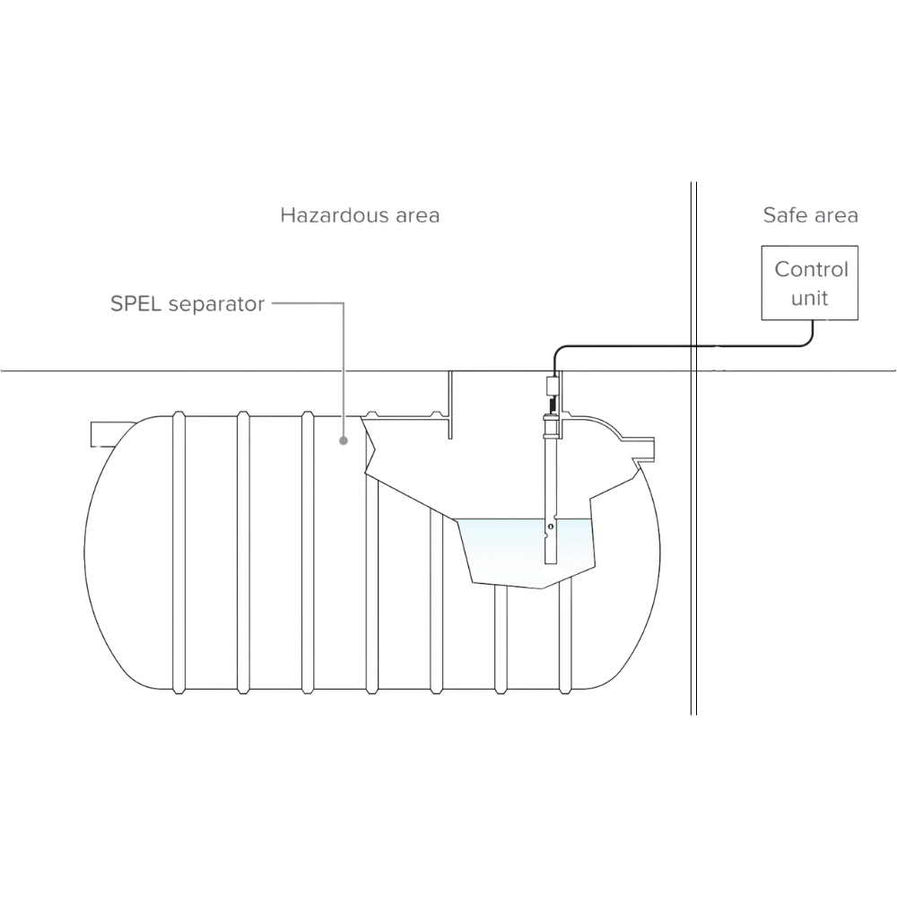
Alarm warnings allow you time to take corrective action ensuring the safe and economic operation of separators preventing oil passing through the separator and polluting watercourses which may result in expensive fines and clean up costs.

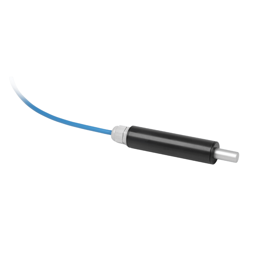
The alarm system and probes guarantee an increased level of safety and requires simple installation for bespoke monitoring of oil and petrol separators.
The SPEL OMS-1 alarm device is specially designed for oil separators. It indicates when it is time to empty the oil separator and thus prevents harmful hydrocarbon emissions to the sewer system.


| Probe | SPEL OMS |
|---|---|
| Principle of operation: | Measurement of conductivity |
| Material: | PVC, AISI 316 |
| Enclosure: | IP68 |
| Temperature: | Operation: 0 °C…+60 °CSafety: -30 °C…+60 °C |
| Cable: | Oil-proof cable 2 x 0,75 mm2, standard length 5m.Other lengths optional. The max. length of the fixed cable is 15 m. Can be extended up to 100m. |
| EMC: | IEC/EN 61000-6-3 (Emission)IEC/EN 61000-6-1 (Immunity) |
| Ex-classification: | II 1 G Ex ia IIA T6 GaAccording to IEC/EN 60079-11 simple apparatus. |
| Manufacturing year:Please see the serial number on the type plate | x xxx x xxxxx xx YY xWhere YY = manufacturing year(e.g. 12 – 2012) |
| Control unit | SPEL OMS-1 |
|---|---|
| Dimensions: | 175 mm × 75 mm × 35 mm (L x H x D) |
| Material: | Polycarbonate |
| Enclosure: | IP65 |
| Operation temperature: | -30 °C…+50 °C |
| Supply voltage: | 230 VAC ± 10 %, 50/60 HzThe device is not equipped with a mains switch. |
| Power consumption: | 1 VA |
| Probes: | OMS probe |
| Relay outputs: | Potential-free relay output 250 V, 5 A, 100 VAOperational delay 10 sec. Relay de-energize at trigger point |
| Electrical safety: | IEC/EN 61010-1, Class II , CAT II |
| Insulation level probe/mains supply voltage: | 375 V (IEC/EN 60079-11) |
| EMC: | EC/EN 61000-6-3 (Emission)IEC/EN 61000-6-1 (Immunity) |
| Ex-classification: | II (1) G [Ex ia] IIB(Ta = -30 °C…+50 °C)VTT 12 ATEX 003XIECEx VTT 12.0001X |
| Electrical parameters: | Uo = 6,6 V Io = 20,2 mA Po = 33,3 mW |
| Manufacturing year:Please see the serial number on the type plate | xxx x xxxxx xx YY xWhere YY = manufacturing year(e.g. 12 – 2012) |

| idOil-OIL | idOil-SLU | idOil-LIQ | |
|---|---|---|---|
| Measurement principle | Conductive | Ultrasonic | Vibration |
| Mounting | Suspension | ||
| Wetted parts | PVC, AISI 316, PA, CR, NBR | PP, AISI 316, PA, CR, Silicon | PVC, aluminium, PA, CR, Viton |
| Weight incl. 5m cable | 395g | 530g | 240g |
| IP classification | IP68 | ||
| Ambient temperature | -30°C…+60°C | -25°C…+60°C | -30°C…+60°C |
| Supply voltage | 12 V DC | ||
| Fixed cable | Length 5m, 2 x 0.75 mm² PUR unshielded | ||
| EMC | IEC/EN 61000-6-2 Emission IEC/EM 61000-6-3 Immunity | ||
| ATEX | VTT 17 ATEX 004X | VTT 17 ATEX 006X | VTT 17 ATEX 005X |
| IECEx | IECEx VTT 17.0002X | IECEx VTT 17.0004X | IECEx VTT 17.0003X |
| Ex-classification | II 1 G Ex ia IIA T5 Ga | II 1 G Ex ia IIB T5 Ga | II 1 G Ex ia IIB T5 Ga |
| Exi Interface Values | Ui=16V, Ii=80 mA, Pi=400 mW | Ui=16V, Ii=80 mA, Pi=400mW | Ui=16 V, Ii=80 mA, Pi=400 mW |
| Max values in IIB | Ci ≤ 5.2 nF, Li ≤ 1.6 mH | Ci ≤ 4.0 nF, Li ≤ 1.6 mH | Ci ≤ 5.2 nF, Li ≤ 1.6 mH |
Detects oil and indicates when the separator’s oil storage is full.
This probe is required in order for a treatment device to comply with BS EN 858.
Monitors the silt layer in the oil separator and indicates when the silt layer has reached its maximum level.
Indicates when the liquid level in the oil separator rises excessively e.g. in an outlet blockage situation.

| IdSet-34 Specs | ||
|---|---|---|
| Mounting | Wall mounting | |
| Enclosure material | Polycarbonate | |
| Weight | 650g | |
| IP classification | IP65 | |
| Indicators | 5 LED lights for alarm and faults,integrated alarm buzzer | |
| Operating environment | Temperature -30 °C…+50 °CMax. elevation above sea level 2 000 mRelative humidity RH 100 % | |
| Supply voltage | 230 V AC ± 10 %, 50/60 Hz | |
| Supply power fuse | Max. 16 A | |
| Power consumption | Max. 8 VA | |
| Relay output | 4 relays, 5 A, 250 V AC/30 V DC, 100 VApotential free changeover contacts | |
| EMC | IEC/EN 61000-6-2IEC/EN 61000-6-3 | |
| Electrical safety | Class II, IEC/EN 61010-1 | |
| Overvoltage category | II | |
| Ex-classification | II (1) G [Ex ia Ga] IIBATEX, IECEx Certified. UKEX Pending. | |
| Exi interface values | Uo = 14.5 V, Io = 78 mA, Po = 367 mW, Ro = 243 Ω | |
| Max value in IIB | Co = 4.0 µF, Lo = 15 mH | |
| Compatible sensors | idOil-LIQ high liquid level sensoridOil-OIL oil sensoridOil-SLU silt sensor | |
| Accessories | LCJ1-1 cable connector for one sensorLCJ1-2 cable connector for two sensorsLCJ1-3 cable connector for three sensorsMounting sets for control unit and sensors | |


LCJ1-1
Cable connector for one probe

LCJ1-2
Cable connector for two probes

LCJ1-3
Cable connector for three probes


N = Neutral conductor
L = Phase conductor
3 = Relay common contact
4 = Contact that opens in an alarm situation
5 = Contact that closes in an alarm situation
6 = Relay common contact
7 = Contact that opens in an alarm situation
8 = Contact that closes in an alarm situation
9 = Relay common contact
10 = Contact that opens in an alarm situation
11 = Contact that closes in an alarm situation
12 = Relay common contact
13 = Contact that opens in an alarm situation
14 = Contact that closes in an alarm situation
| IdOil-30 Specs | ||
|---|---|---|
| Mounting | Wall mounting | |
| Enclosure material | Polycarbonate | |
| Weight | 780g | |
| IP classification | IP65 | |
| Display | 4 line monochrome LCD | |
| Ambient temperature | -30°C…+60°C | |
| Supply voltage | 100-240V AC, 50/60 Hz | |
| Supply power fuse | Max. 10 A | |
| Power consumption | Max. 12 VA | |
| Relay outputs | 5 A, 250 V AC/30 V DC, 100 VA potential free changeover contacts, 2 pcs | |
| EMC | IEC/EN 61000-6-2IEC/EN 61000-6-3 | |
| Electrical safety | Class I, CAT II IEC/EN 61010-1, UL 61010-1CAN/CSA-C 22.2 NO. 61010-1-12 | |
| Ex-classification | II (1) G [Ex is Ga] IIB | |
| ATEXIECEx | VTT 16 ATEX 018XIECEx VTT 16.0005X | |
| Exi interface values | Uo = 14.5 V, Io = 78mA, Po = 367 mW, R = 243 Ω | |
| Max values in IIB | Co = 4.0 μF, Lo = 16.7 mH | |
| Compatible probes | idOil-LIQ high liquid level probesidOil-OIL oil probeidOil-SLU silt probe | |
| Accessories | LCJ1-1 cable connector for one probeLCJ1-2 cable connector for two probesLCJ1-3 cable connector for three probesLMS-SAS5 mounting set for one probe | |


LCJ1-1
Cable connector for one probe
LCJ1-2
Cable connector for two probes
LCJ1-3
Cable connector for three probes

The idOil Solar is a solar powered oil separator alarm, it’s ideal for remote applications/off-grid areas or where supplying a dedicated single phase power source is complicated.
The solar powered control system is a modular platform within the idOil range and can accommodate a range of probes and control panels to meet clients specific requirements. Please contact our team for more details.
As per the illustrations below, this system can be supplied as the basic solar panel platform or include an optional flashing beacon, it also has the added benefit of being able to connect to autodialler/3G modem. If the alarm is activated, the beacon light will flash and/or an alarm message will be sent via an SMS/mobile network, this alarm message can be sent to up to five different pre-programmed mobile numbers.

| Solar Alarm Specs | ||
|---|---|---|
| Enclosure Material | Polycarbonate | |
| Weight | 8000g | |
| IP Classification | IP43 with two ventilation devices | |
| Ambient Temperature | -30 °C…+60 °C | |
| Supply Voltage | 11-17 V DC | |
| Compatible Probes | idOil-LIQ, idOil-OIL, idOil-SLU | |
| Relay Outputs | 5 A, 30 V DC, 100 VA potential free, 2 pcs | |
| EMC | IEC/EN 61000-6-2IEC/EN 61000-6-3 | |
| Electrical Safety | Class III, IEC/EN 61010-1, UL 61010-1CAN/CSA-C 22.2 NO. 61010-1-12 | |
| Overvoltage Category | ||
| ATEX | VTT 16 ATEX 018X | |
| IECEx | IECEx VTT 16.0005X | |
| Ex-classification | II (1) G [Ex ia Ga] IIB | |


Fill out the form below with your details and any info you wish to be considered by our team and we will be in touch shortly.
This is the SPEL Puraceptor single chamber model sizing chart. For the difference between single and two chamber models see the explanation below under operation.
Model | Series | Nominal Size (NS) | Catchment Area (m2) | Oil Storage (L) | Silt Capacity (L) | Overall Length* (mm) | Overall Diameter (mm) | Inlet Invert (mm) | Base to Inlet (mm) | Base to Outlet (mm) | Optimum In/Out Pipe Diameter** (mm) | Number of Access Shafts(dia. mm) | ||||
Flow (l/s) | L | A | B | C | 450 | 600 | 750 | 900 | 1200 | |||||||
P004 1C/SC | 200 | 4 | 222 | 40 | 400 | 1,720 | 1,225 | 630 | 1,110 | 1,050 | 160 | – | – | 1 | – | – |
P006 1C/SC | 200 | 6 | 333 | 60 | 600 | 2,310 | 1,225 | 630 | 1,110 | 1,050 | 160 | – | – | 1 | – | – |
P010 1C/SC | 200 | 10 | 556 | 100 | 1,000 | 3,410 | 1,225 | 630 | 1,110 | 1,050 | 160 | – | – | 1 | – | – |
P015 1C/SC | 300 | 15 | 833 | 150 | 1,500 | 3,200 | 1,875 | 350 | 1,800 | 1,740 | 225 | 1 | – | 1 | – | – |
P020 1C/SC | 300 | 20 | 1,111 | 200 | 2,000 | 3,540 | 1,875 | 350 | 1,800 | 1,740 | 225 | – | 1 | 1 | – | – |
FP 1C/SC | 300 | 20 | 1,111 | 200 | 2,000 | 4,290 | 1,875 | 350 | 1,800 | 1,740 | 225 | – | 1 | – | – | |
P030 1C/SC | 300 | 30 | 1,667 | 300 | 3,000 | 4,420 | 1,875 | 390 | 1,760 | 1,700 | 300 | – | 1 | – | 1 | – |
P040 1C/SC | 300 | 40 | 2,222 | 400 | 4,000 | 5,760 | 1,875 | 390 | 1,760 | 1,700 | 300 | – | 1 | – | 1 | – |
P050 1C/SC | 300 | 50 | 2,778 | 500 | 5,000 | 7,060 | 1,875 | 390 | 1,760 | 1,700 | 300 | – | 1 | – | 1 | – |
P065 1C/SC | 400 | 65 | 3,611 | 650 | 6,500 | 4,860 | 2,700 | 425 | 2,625 | 2,525 | 300 | – | 1 | – | 2 | – |
P080 1C/SC | 400 | 80 | 4,444 | 800 | 8,000 | 5,700 | 2,700 | 425 | 2,625 | 2,525 | 300 | – | 1 | – | 2 | – |
P100 1C/SC | 400 | 100 | 5,555 | 1,000 | 10,000 | 7,400 | 2,700 | 475 | 2,575 | 2,475 | 450 | – | 1 | – | 2 | – |
P125 1C/SC | 400 | 125 | 6,944 | 1,250 | 12,500 | 8,580 | 2,700 | 475 | 2,575 | 2,475 | 450 | – | – | 1 | 2 | – |
P150 1C/SC | 400 | 150 | 8,333 | 1,500 | 15,000 | 10,180 | 2,700 | 475 | 2,575 | 2,475 | 450 | – | – | 1 | 2 | – |
P165 1C/SC | 400 | 165 | 9,166 | 1,650 | 16,500 | 11,200 | 2,700 | 500 | 2,550 | 2,450 | 450 | – | 2 | 1 | 1 | – |
P200 1C/SC | 400 | 200 | 11,110 | 2,000 | 20,000 | 13,710 | 2,700 | 660 | 2,390 | 2,290 | 600 | – | 2 | 1 | 1 | – |
P250 1C/SC | 400 | 250 | 13,888 | 2,500 | 25,000 | 16,750 | 2,700 | 660 | 2,390 | 2,290 | 600 | – | 2 | 1 | 2 | – |
P280 1C/SC | 400 | 280 | 15,555 | 2,800 | 28,000 | 18,800 | 2,700 | 660 | 2,390 | 2,290 | 600 | – | 1 | 2 | 2 | – |
P300 1C/SC | 500 | 300 | 16,665 | 3,000 | 30,000 | 12,410 | 3,650 | 805 | 3,070 | 2,970 | 750 | – | 1 | 2 | 2 | – |
P400 1C/SC | 500 | 400 | 22,220 | 4,000 | 40,000 | 15,760 | 3,650 | 805 | 3,070 | 2,970 | 750 | – | 2 | 2 | 2 | – |
P500 1C/SC | 500 | 500 | 27,775 | 5,000 | 50,000 | 20,530 | 3,650 | 955 | 2,920 | 2,820 | 900 | – | 2 | 2 | 1 | 1 |
P500 1C/SC | 600 | 500 | 27,775 | 5,000 | 50,000 | 16,040 | 4,150 | 925 | 3,250 | 3,150 | 900 | – | 2 | 2 | 1 | 1 |
P600 1C/SC | 600 | 600 | 33,330 | 6,000 | 60,000 | 19,080 | 4,150 | 925 | 3,250 | 3,150 | 900 | – | 2 | 2 | – | 2 |
P700 1C/SC | 600 | 700 | 38,888 | 7,000 | 70,000 | 21,460 | 4,150 | 925 | 3,250 | 3,150 | 900 | – | 3 | 2 | 3 | – |
P800 1C/SC | 600 | 800 | 44,440 | 8,000 | 80,000 | 23,020 | 4,150 | 925 | 3,250 | 3,150 | 900 | – | 3 | 2 | 2 | 1 |
All of the above models are available without silt capacity, below are selected models for size comparison. The P1000 model is only available in non silt format. | ||||||||||||||||
P050 1C | 300 | 50 | 2,778 | 500 | – | 5,070 | 1875 | 390 | 1,760 | 1,700 | 300 | – | – | – | 1 | – |
P065 1C | 400 | 65 | 3,611 | 650 | – | 3,710 | 2,700 | 425 | 2,625 | 2,525 | 300 | – | – | 2 | – | |
P100 1C | 400 | 100 | 5,555 | 1,000 | – | 5,250 | 2,700 | 475 | 2,575 | 2,475 | 450 | – | – | 2 | – | |
P125 1C | 400 | 125 | 6,944 | 1,250 | – | 6,090 | 2,700 | 475 | 2,575 | 2,475 | 450 | – | – | – | 2 | – |
P165 1C | 400 | 165 | 9,166 | 1,650 | – | 7,960 | 2,700 | 500 | 2,550 | 2,450 | 450 | – | 2 | 1 | – | |
P250 1C | 400 | 250 | 13,888 | 2,500 | – | 11,830 | 2,700 | 660 | 2,390 | 2,290 | 600 | – | 2 | 2 | – | |
P300 1C | 400 | 300 | 16,665 | 3,000 | – | 14,120 | 2,700 | 660 | 2,390 | 2,290 | 600 | – | 2 | 2 | – | |
P500 1C | 500 | 500 | 27,775 | 5,000 | – | 14,340 | 3,650 | 955 | 2,920 | 2,820 | 900 | – | 2 | 2 | 1 | 1 |
P500 1C | 600 | 500 | 27,775 | 5,000 | – | 11,470 | 4,150 | 925 | 3,250 | 3,150 | 900 | – | 2 | 2 | 1 | 1 |
P700 1C | 600 | 700 | 38,888 | 7,000 | – | 15,880 | 4,150 | 925 | 3,250 | 3,150 | 900 | – | 3 | 2 | 3 | – |
P1000 1C | 600 | 1,000 | 55,550 | 10,000 | – | 21,407 | 4,150 | 925 | 3,250 | 3,150 | 900 | – | 3 | 2 | 1 | 3 |
*Overall length subject to inlet/outlet and orientation.
**SPEL Separators are designed for a maximum flow (NS/NSB) but can be fitted with larger than the recommended maximum connection size IN/OUT or with the addition of adapters providing the maximum flow (NS/NSB) cannot be exceeded or any increase in the operating level in the SPEL Separator to cause the captured pollutants to escape into the vent connections or through access shaft connections. Any overriding of the above criteria could jeopardise performance to the European Standard BS EN 858-1.
Note: Model FP1C/SC is a special Forecourt separator with 7600 litre spillage holding capacity. Click here for more information on Forecourt Separators.
This is the SPEL Puraceptor two chamber model sizing chart. For the difference between single and two chamber models see the explanation below under operation.
Model | Series | Nominal Size (NS) | Catchment Area (m2) | Oil Storage (L) | Silt Capacity (L) | Overall Length* (mm) | Overall Diameter (mm) | Inlet Invert (mm) | Base to Inlet (mm) | Base to Outlet (mm) | Optimum In/Out Pipe Diameter** (mm) | Number of Access Shafts(dia. mm) | ||||
Flow (l/s) | L | A | B | C | 450 | 600 | 750 | 900 | 1200 | |||||||
P006 2C/SC | 200 | 6 | 333 | 60 | 600 | 3,050 | 1,225 | 340 | 1,200 | 1,140 | 160 | – | 1 | 1 | – | – |
P010 2C/SC | 200 | 10 | 556 | 100 | 1,000 | 4,690 | 1,225 | 340 | 1,200 | 1,140 | 160 | – | 1 | 1 | – | – |
P015 2C/SC | 300 | 15 | 833 | 150 | 1,500 | 4,015 | 1,875 | 350 | 1,800 | 1,740 | 225 | – | – | 2 | – | – |
P020 2C/SC | 300 | 20 | 1,111 | 200 | 2,000 | 4,015 | 1,875 | 350 | 1,800 | 1,740 | 225 | – | – | 2 | – | – |
FP 2C/SC*** | 300 | 20 | 1,111 | 200 | 2,000 | 5,500 | 1,875 | 350 | 1,800 | 1,740 | 225 | – | – | 2 | – | – |
P025 2C/SC | 300 | 25 | 1,389 | 250 | 2,500 | 4,290 | 1,875 | 350 | 1,800 | 1,740 | 225 | – | – | 2 | – | – |
P030 2C/SC | 300 | 30 | 1,667 | 300 | 3,000 | 4,420 | 1,875 | 390 | 1,760 | 1,700 | 300 | – | 1 | 2 | – | – |
P035 2C/SC | 300 | 35 | 1,944 | 350 | 3,500 | 5,070 | 1,875 | 390 | 1,760 | 1,700 | 300 | – | 1 | 2 | – | – |
P040 2C/SC | 300 | 40 | 2,222 | 400 | 4,000 | 5,760 | 1,875 | 390 | 1,760 | 1,700 | 300 | – | 1 | 2 | – | – |
P050 2C/SC | 300 | 50 | 2,778 | 500 | 5,000 | 7,060 | 1,875 | 390 | 1,760 | 1,700 | 300 | – | 1 | 2 | – | – |
P065 2C/SC | 300 | 65 | 3,611 | 650 | 6,500 | 9,180 | 1,875 | 390 | 1,760 | 1,700 | 300 | 1 | – | 2 | – | – |
P080 2C/SC | 400 | 80 | 4,444 | 800 | 8,000 | 5,700 | 2,700 | 425 | 2,625 | 2,525 | 300 | – | – | 1 | 1 | – |
P100 2C/SC | 400 | 100 | 5,555 | 1,000 | 10,000 | 7,400 | 2,700 | 475 | 2,575 | 2,475 | 450 | – | – | 1 | 1 | – |
P125 2C/SC | 400 | 125 | 6,944 | 1,250 | 12,500 | 8,580 | 2,700 | 475 | 2,575 | 2,475 | 450 | – | – | 2 | 1 | – |
P150 2C/SC | 400 | 150 | 8,333 | 1,500 | 15,000 | 10,180 | 2,700 | 500 | 2,550 | 2,450 | 450 | – | – | 2 | 1 | – |
P200 2C/SC | 400 | 200 | 11,110 | 2,000 | 20,000 | 13,710 | 2,700 | 660 | 2,390 | 2,290 | 600 | – | 1 | 2 | 1 | – |
P250 2C/SC | 400 | 250 | 13,888 | 2,500 | 25,000 | 16,752 | 2,700 | 660 | 2,390 | 2,290 | 600 | – | 2 | 1 | 2 | – |
P300 2C/SC | 500 | 300 | 16,665 | 3,000 | 30,000 | 12,530 | 3,650 | 675 | 3,200 | 3,100 | 600 | – | 1 | 2 | – | 1 |
P400 2C/SC | 500 | 400 | 22,220 | 4,000 | 40,000 | 15,980 | 3,650 | 675 | 3,200 | 3,100 | 600 | – | 2 | 2 | 2 | – |
P500 2C/SC | 500 | 500 | 27,775 | 5,000 | 50,000 | 20,530 | 3,650 | 955 | 2,920 | 2,820 | 900 | – | 2 | 2 | 1 | 1 |
P500 2C/SC | 600 | 500 | 27,775 | 5,000 | 50,000 | 16,260 | 4,150 | 925 | 3,250 | 3,150 | 900 | – | 2 | 1 | 1 | 1 |
P600 2C/SC | 600 | 600 | 33,330 | 6,000 | 60,000 | 19,080 | 4,150 | 925 | 3,250 | 3,150 | 900 | – | 2 | 2 | 3 | – |
P700 2C/SC | 600 | 700 | 38,888 | 7,000 | 70,000 | 22,270 | 4,150 | 925 | 3,250 | 3,150 | 900 | – | 3 | 2 | 3 | – |
P800 2C/SC | 600 | 800 | 44,440 | 8,000 | 80,000 | 23,020 | 4,150 | 925 | 3,250 | 3,150 | 900 | – | 3 | 2 | 2 | 1 |
P900 2C/SC | 600 | 900 | 50,000 | 9,000 | 90,000 | 24,658 | 4,150 | 925 | 3,250 | 3,150 | 900 | – | 3 | 2 | 1 | 2 |
*Overall length subject to inlet/outlet and orientation.
**SPEL Separators are designed for a maximum flow (NS/NSB) but can be fitted with larger than the recommended maximum connection size IN/OUT or with the addition of adapters providing the maximum flow (NS/NSB) cannot be exceeded or any increase in the operating level in the SPEL Separator to cause the captured pollutants to escape into the vent connections or through access shaft connections. Any overriding of the above criteria could jeopardise performance to the European Standard BS EN 858-1.
Note: Model FP2C/SC is a special Forecourt separator with 7600 litre spillage holding capacity. Click here for more information on Forecourt Separators.
| Model | Series | Meals per Day* | NSG | Tank Length (mm) | Internal Diameter (mm) | Overall Capacity (L) | Grease Capacity (L) | Inlet Invert (m) | Base to Inlet (mm) | Base to Outlet(mm) | Optimum In/Out Pipe Diameter** (mm) | Number of Access Shafts (dia. mm) |
|---|---|---|---|---|---|---|---|---|---|---|---|---|
| L | A | B | C | 600 | ||||||||
| GS200/2000 | 200 | 400 | 4 | 2,040 | 1,200 | 2,000 | 160 | 1,020 | 1,000 | 940 | 160 | 2 |
| GS200/3000 | 200 | 600 | 6 | 2,930 | 1,200 | 3,000 | 240 | 1,020 | 1,000 | 940 | 160 | 2 |
| GS200/4000 | 200 | 900 | 9 | 3,810 | 1,200 | 4,000 | 360 | 1,020 | 1,000 | 940 | 160 | 2 |
| GS200/5000 | 200 | 1100 | 11 | 4,700 | 1,200 | 5,000 | 440 | 1,020 | 1,000 | 940 | 160 | 2 |
| GS200/6000 | 200 | 1400 | 14 | 5,578 | 1,200 | 6,000 | 560 | 1,020 | 1,000 | 940 | 160 | 2 |
| GS300/5860 | 300 | 1400 | 14 | 2,690 | 1,800 | 5,860 | 560 | 1,600 | 1,600 | 1,550 | 160 | 2 |
| GS300/9270 | 300 | 1800 | 18 | 4,015 | 1,800 | 9,270 | 720 | 1,600 | 1,600 | 1,550 | 160 | 2 |
| GS300/18200 | 300 | 4000 | 40 | 7,620 | 1,800 | 18,200 | 1600 | 1,600 | 1,600 | 1,550 | 160 | 2 |
| Model | Series | Max. Flow* | Silt Capacity (L) | Overall Length* | Internal Diameter (mm) | Opt In/Out Pipe Diameter (mm) | Number of Access Shafts (dia. mm) | Inlet Invert (mm) |
|---|---|---|---|---|---|---|---|---|
| Flow (l/s) | L | 600 | A | |||||
| WDS 200/1000 | 200 | 1.1 | 250 | 1.17 | 1,200 | 160mm | 1 | – |
| WDS 200/2000 | 200 | 2.2 | 500 | 2.05 | 1,200 | 160mm | 1 | – |
| WDS 200/3000 | 200 | 3.3 | 700 | 2.93 | 1,200 | 160mm | 1 | – |
| WDS 200/4000 | 200 | 4.5 | 1,000 | 3.82 | 1,200 | 160mm | 1 | – |
| WDS 200/5000 | 200 | 5.6 | 1,250 | 4.7 | 1,200 | 160mm | 1 | – |
| WDS 200/6000 | 200 | 6.7 | 1,500 | 5.59 | 1,200 | 160mm | 1 | – |
| WDS 200/7000 | 200 | 7.8 | 1,750 | 6.48 | 1,200 | 160mm | 1 | – |
| WDS 200/8000 | 200 | 9 | 2,000 | 7.36 | 1,200 | 160mm | 1 | – |
| WDS 200/9000 | 200 | 10 | 2,250 | 8.25 | 1,200 | 160mm | 1 | – |
| WDS 200/10,000 | 200 | 11 | 2,500 | 9.13 | 1,200 | 160mm | 1 | – |
| WDS 300/4000 | 300 | 5 | 1,000 | 1.95 | 1,800 | 160mm | 1 | – |
| WDS 300/6000 | 300 | 7 | 1,500 | 2.76 | 1,800 | 160mm | 1 | – |
| WDS 300/8000 | 300 | 9 | 2,000 | 3.54 | 1,800 | 160mm | 1 | – |
| WDS 300/10,000 | 300 | 12 | 2,500 | 4.29 | 1,800 | 160mm | 1 | – |
| Model | Series | Nominal Size (NB) | Catchment Area (M2) | Oil Storage (L) | Silt Capacity (L) | Overall Length* (mm) | Overall Diameter (mm) | Inlet Invert (mm) | Base to Inlet (mm) | Base to Outlet (mm) | Optimum In/Out pipe Diameter** (mm) | Number of Access Shafts (dia. mm) | ||||
|---|---|---|---|---|---|---|---|---|---|---|---|---|---|---|---|---|
| Flow (l/s) | A | B | C | 450 | 600 | 750 | ||||||||||
| FR004 SC | 200 | 4 | 222 | 40 | 400 | 1,720 | 1225 | 630 | 1,110 | 1,050 | 160 | 1 | ||||
| FR006 SC | 200 | 6 | 333 | 60 | 600 | 2,270 | 1,225 | 630 | 1,110 | 1,050 | 160 | 1 | ||||
| FR010 SC | 200 | 10 | 556 | 100 | 1,000 | 3,410 | 1,225 | 630 | 1,110 | 1,050 | 160 | 1 | ||||
| FR015 SC | 300 | 15 | 833 | 150 | 1,500 | 2,760 | 1,875 | 350 | 1,800 | 1,740 | 225 | 1 | ||||
| FR020 SC | 300 | 20 | 1,111 | 200 | 2,000 | 3,200 | 1,875 | 350 | 1,800 | 1,740 | 225 | 1 | ||||
| FS2 SC | 300 | 20 | 1,111 | 200 | 2,000 | 4,290 | 1,875 | 350 | 1,800 | 1,740 | 225 | 1 | ||||
| FR030 SC | 300 | 30 | 1,667 | 300 | 3,000 | 4,420 | 1,875 | 390 | 1,760 | 1,700 | 300 | 1 | ||||
| FR040 SC | 300 | 40 | 2,222 | 400 | 4,000 | 5,760 | 1,875 | 390 | 1,760 | 1,700 | 300 | 1 | ||||
| FR050 SC | 300 | 50 | 2,778 | 500 | 5,000 | 7,060 | 1,875 | 390 | 1,760 | 1,700 | 300 | 1 | ||||
| FR065 SC | 400 | 65 | 3,611 | 650 | 6,500 | 4,810 | 2,700 | 425 | 2,625 | 2,525 | 300 | 1 | 1 | |||
| FR080 SC | 400 | 80 | 4,444 | 800 | 8,000 | 5,700 | 2,700 | 425 | 2,625 | 2,525 | 300 | 1 | 1 | |||
| FR100 SC | 400 | 100 | 5,555 | 1,000 | 10,000 | 7,400 | 2,700 | 475 | 2,575 | 2,475 | 450 | 1 | 1 | |||
| FR125 SC | 400 | 125 | 6,944 | 1,250 | 12,500 | 8,580 | 2,700 | 475 | 2,575 | 2,475 | 450 | 1 | 1 | |||
| FR150 SC | 400 | 150 | 8,333 | 1,500 | 15,000 | 10,180 | 2,700 | 475 | 2,575 | 2,475 | 450 | 1 | 1 | |||
| FR165 SC | 400 | 165 | 9,166 | 1,650 | 16,500 | 11,200 | 2,700 | 500 | 2,550 | 2,450 | 450 | 2 | ||||
| FR200 SC | 400 | 200 | 11,110 | 2,000 | 20,000 | 13,710 | 2,700 | 660 | 2,390 | 2,290 | 600 | 2 | ||||
| FR250 SC | 400 | 250 | 13,888 | 2,500 | 25,000 | 16,750 | 2,700 | 660 | 2,390 | 2,290 | 600 | 2 | ||||
| Model | Series | Nominal Size (NB) | Catchment Area (M2) | Oil Storage (L) | Silt Capacity (L) | Overall Length* (mm) | Overall Diameter (mm) | Inlet Invert (mm) | Base to Inlet (mm) | Base to Outlet (mm) | Optimum In/Out pipe Diameter** (mm) | Number of Access Shafts (dia. mm) | ||||
|---|---|---|---|---|---|---|---|---|---|---|---|---|---|---|---|---|
| Flow (l/s) | A | B | C | 450 | 600 | 750 | ||||||||||
| FR040 | 300 | 40 | 2,222 | 400 | 4,020 | 1,875 | 390 | 1,760 | 1,700 | 300 | 1 | |||||
| FR050 | 300 | 50 | 2,778 | 500 | 5,070 | 1,875 | 390 | 1,760 | 1,700 | 300 | 1 | |||||
| FR065 | 400 | 65 | 3,611 | 650 | 3,710 | 2,700 | 425 | 2,625 | 2,525 | 300 | 1 | 1 | ||||
| FR080 | 400 | 80 | 4,444 | 800 | 4,400 | 2,700 | 425 | 2,625 | 2,525 | 300 | 1 | 1 | ||||
| FR100 | 400 | 100 | 5,555 | 1000 | 5,250 | 2,700 | 475 | 2,575 | 2,475 | 450 | 1 | 1 | ||||
| FR125 | 400 | 125 | 6,944 | 1250 | 6,090 | 2,700 | 475 | 2,575 | 2,475 | 450 | 1 | 1 | ||||
| FRI50 | 400 | 150 | 8,333 | 1500 | 7,400 | 2,700 | 475 | 2,575 | 2,475 | 450 | 1 | 1 | ||||
| FR165 | 400 | 165 | 9,166 | 1650 | 7,960 | 2,700 | 500 | 2,550 | 2,450 | 450 | 2 | |||||
| FR200 | 400 | 200 | 11,110 | 2000 | 9,600 | 2,700 | 660 | 2,390 | 2,290 | 600 | 2 | |||||
| FR250 | 400 | 250 | 13,888 | 2500 | 11,830 | 2,700 | 660 | 2,390 | 2,290 | 600 | 2 | |||||
| FR300 | 400 | 300 | 16,665 | 3000 | 14,120 | 2,700 | 660 | 2,390 | 2,290 | 600 | 2 | |||||
| FR400 | 500 | 400 | 222,222 | 4,000 | optional | * | 3,650 | – | 3 | – | ||||||
*Overall length subject to inlet/outlet size and orientation
**SPEL Separators are designed for a maximum flow (NS/NSB) but can be fitted with larger than the recommended maximum connection size IN/OUT or with the addition of adapters providing the maximum flow (NS/NSB) cannot be exceeded or any increase in the operating level in the SPEL Separator to cause the captured pollutants to escape into the vent connections or through access shaft connections. Any overriding of the above criteria could jeopardise performance to the European Standard BS EN 858-1.
Note: Model FS2SC is a special forecourt unit with 7600 litre spillage holding capacity.
Model | Series | Nominal Size (NS) | Catchment Area (m2) | Oil Storage (L) | Silt Capacity (L) | Overall Length (mm) | Inlet Invert (mm) | Base to Inlet (mm) | Base to Outlet (mm) | Optimum Inlet dia.** (mm) |
Flow (l/s) | L | |||||||||
P006 2C/SC/M | 300 | 6 | 333 | 60 | 600 | 3,200 | 540 | 1,610 | 1,550 | 160 |
P010 2C/SC/M | 300 | 10 | 556 | 100 | 1,000 | 5,070 | 540 | 1,610 | 1,550 | 160 |
P015 2C/SC/M | 300 | 15 | 833 | 150 | 1,500 | 6,570 | 550 | 1,600 | 1,500 | 225 |
P020 2C/SC/M | 400 | 20 | 1,111 | 200 | 2,000 | 5,250 | 625 | 2,425 | 2,325 | 225 |
P025 2C/SC/M | 400 | 25 | 1,389 | 250 | 2,500 | 6,170 | 625 | 2,425 | 2,325 | 225 |
P030 2C/SC/M | 400 | 30 | 1,667 | 300 | 3,000 | 7,400 | 625 | 2,425 | 2,325 | 300 |
P040 2C/SC/M | 400 | 40 | 2,222 | 400 | 4,000 | 9,930 | For details, please contact our Technical Sales Team | 300 | ||
P060 2C/SC/M | 400 | 60 | 3,333 | 600 | 6,000 | 13,710 | For details, please contact our Technical Sales Team | 300 | ||
P080 2C/SC/M | 500 | 80 | 4,444 | 800 | 8,000 | 10,040 | For details, please contact our Technical Sales Team | 300 | ||
P100 2C/SC/M | 500 | 100 | 5,555 | 1,000 | 10,000 | 12,530 | For details, please contact our Technical Sales Team | 450 | ||
| Model | Series | Nominal Size (NS) | Catchment Area (m2) | Oil Storage (L) | Silt Capacity (L) | Overall Length* (mm) | Overall Diameter (mm) | Inlet Invert (mm) | Base to Inlet (mm) | Base to Outlet (mm) | Optimum In/Out Pipe Diameter** (mm) | Number of Access Shafts (dia. mm) | ||||||
|---|---|---|---|---|---|---|---|---|---|---|---|---|---|---|---|---|---|---|
| Flow (l/s) | L | A | B | C | 450 | 750 | 900 | 1200 | ||||||||||
| P006 2C/SC/NG | 200 | 6 | 333 | 60 | 600 | 3,050 | 1225 | 427 | 1,110 | 1,050 | 160 | – | 1 | 1 | – | |||
| P010 2C/SC/NG | 200 | 10 | 556 | 100 | 1,000 | 4,700 | 1,225 | 427 | 1,110 | 1,050 | 160 | – | 3 | – | – | |||
| P015 2C/SC/NG | 300 | 15 | 833 | 150 | 1,500 | 4,020 | 1,875 | 540 | 1,610 | 1,550 | 225 | – | 3 | – | – | |||
| P020 2C/SC/NG | 300 | 20 | 1,111 | 200 | 2,000 | 4,020 | 1,875 | 540 | 1,610 | 1,550 | 225 | – | 3 | – | – | |||
| P025 2C/SC/NG | 300 | 25 | 1,389 | 250 | 2,500 | 4,290 | 1,875 | 540 | 1,610 | 1,550 | 225 | – | 3 | – | – | |||
| P030 2C/SC/NG | 300 | 30 | 1,667 | 300 | 3,000 | 5,070 | 1,875 | 550 | 1,600 | 1,500 | 300 | – | 2 | 1 | – | |||
| P040 2C/SC/NG | 300 | 40 | 2,222 | 400 | 4,000 | 6,570 | 1,875 | 550 | 1,600 | 1,500 | 300 | – | 2 | 1 | – | |||
| P050 2C/SC/NG | 300 | 50 | 2,778 | 500 | 5,000 | 8,260 | 1,875 | 550 | 1,600 | 1,500 | 300 | – | 2 | 1 | – | |||
| P065 2C/SC/NG | 300 | 65 | 3,611 | 650 | 6,500 | 10,220 | 1,875 | 550 | 1,600 | 1,500 | 300 | 1 | 2 | 1 | – | |||
| P065 2C/SC/NG | 400 | 65 | 3,611 | 650 | 6,500 | 5,470 | 2,700 | 665 | 2,385 | 2,285 | 300 | 1 | 1 | 1 | – | |||
| P080 2C/SC/NG | 400 | 80 | 4,444 | 800 | 8,000 | 6,170 | 2,700 | 665 | 2,385 | 2,285 | 300 | 1 | 1 | 1 | – | |||
| P100 2C/SC/NG | 400 | 100 | 5,555 | 1,000 | 10,000 | 7400 | 2,700 | 665 | 2385 | 2285 | 450 | 1 | 1 | 1 | – | |||
| P125 2C/SC/NG | 400 | 125 | 6,944 | 1,250 | 12,500 | 9,600 | 2,700 | 765 | 2,285 | 2,185 | 450 | 1 | 2 | – | 1 | |||
| P150 2C/SC/NG | 400 | 150 | 8,333 | 1,500 | 15,000 | 11,200 | 2,700 | 790 | 2,280 | 2,180 | 450 | 1 | 2 | – | 1 | |||
| P200 2C/SC/NG | 400 | 200 | 11,110 | 2,000 | 20,000 | 16,400 | 2,700 | 940 | 2,130 | 2,030 | 600 | 2 | 2 | – | 1 | |||
| P300 2C/SC/NG | 500 | 300 | 16,665 | 3,000 | 30,000 | 12,530 | 3,650 | 875 | 3,000 | 2,900 | 600 | 2 | 2 | – | 1 | |||
| P400 2C/SC/NG | 500 | 400 | 22,220 | 4,000 | 40,000 | 16,330 | 3,650 | 875 | 3,000 | 2,900 | 600 | 3 | 2 | 2 | – | |||
| Model | Series | Nominal Size (NS) | Catchment Area (m2) | Oil Storage (L) | Silt Capacity (L) | Overall Length* (mm) | Overall Diameter (mm) | Inlet Invert (mm) | Base to Inlet (mm) | Base to Outlet (mm) | Optimum In/Out Pipe Diameter* (mm) | Number of Access Shafts (dia. mm) | ||||
|---|---|---|---|---|---|---|---|---|---|---|---|---|---|---|---|---|
| Flow (l/s) | L | A | B | C | 750 | 900 | 1200 | |||||||||
| FP 1C/SCClass 1 Forecourt SeparatorSingle Chamber with Silt Capture | 300 | 20 | 1,111 | 200 | 2,000 | 4,290 | 1,875 | 350 | 1,800 | 1,740 | 225 | 1 | – | – | ||
| FP 2C/SCClass 1 Forecourt SeparatorTwo Chamber with Silt Capture | 300 | 20 | 1,111 | 200 | 2,000 | 5,500 | 1,875 | 350 | 1,800 | 1,740 | 225 | 2 | – | – | ||
| FS2 SCClass 2 Forecourt SeparatorSingle Chamber with Silt Capture | 300 | 20 | 1,111 | 200 | 2,000 | 4,290 | 1,875 | 350 | 1,800 | 1,740 | 225 | – | – | 1 | ||
Model | Series | Nominal Size (NS) | Catchment Area (m2) | Oil Storage (L) | Silt Capacity (L) | Overall Length* (mm) | Overall Diameter (mm) | Inlet Invert (mm) | Base to Inlet (mm) | Base to Outlet (mm) | Optimum In/Out Pipe Diameter** (mm) | Number of Access Shafts(dia. mm) | ||||
Flow (l/s) | L | A | B | C | 450 | 600 | 750 | 900 | 1200 | |||||||
P006 2C/SC | 200 | 6 | 333 | 60 | 600 | 3,050 | 1,225 | 340 | 1,200 | 1,140 | 160 | – | 1 | 1 | – | – |
P010 2C/SC | 200 | 10 | 556 | 100 | 1,000 | 4,690 | 1,225 | 340 | 1,200 | 1,140 | 160 | – | 1 | 1 | – | – |
P015 2C/SC | 300 | 15 | 833 | 150 | 1,500 | 4,015 | 1,875 | 350 | 1,800 | 1,740 | 225 | – | – | 2 | – | – |
P020 2C/SC | 300 | 20 | 1,111 | 200 | 2,000 | 4,015 | 1,875 | 350 | 1,800 | 1,740 | 225 | – | – | 2 | – | – |
FP 2C/SC*** | 300 | 20 | 1,111 | 200 | 2,000 | 5,500 | 1,875 | 350 | 1,800 | 1,740 | 225 | – | – | 2 | – | – |
P025 2C/SC | 300 | 25 | 1,389 | 250 | 2,500 | 4,290 | 1,875 | 350 | 1,800 | 1,740 | 225 | – | – | 2 | – | – |
P030 2C/SC | 300 | 30 | 1,667 | 300 | 3,000 | 4,420 | 1,875 | 390 | 1,760 | 1,700 | 300 | – | 1 | 2 | – | – |
P035 2C/SC | 300 | 35 | 1,944 | 350 | 3,500 | 5,070 | 1,875 | 390 | 1,760 | 1,700 | 300 | – | 1 | 2 | – | – |
P040 2C/SC | 300 | 40 | 2,222 | 400 | 4,000 | 5,760 | 1,875 | 390 | 1,760 | 1,700 | 300 | – | 1 | 2 | – | – |
P050 2C/SC | 300 | 50 | 2,778 | 500 | 5,000 | 7,060 | 1,875 | 390 | 1,760 | 1,700 | 300 | – | 1 | 2 | – | – |
P065 2C/SC | 300 | 65 | 3,611 | 650 | 6,500 | 9,180 | 1,875 | 390 | 1,760 | 1,700 | 300 | 1 | – | 2 | – | – |
P080 2C/SC | 400 | 80 | 4,444 | 800 | 8,000 | 5,700 | 2,700 | 425 | 2,625 | 2,525 | 300 | – | – | 1 | 1 | – |
P100 2C/SC | 400 | 100 | 5,555 | 1,000 | 10,000 | 7,400 | 2,700 | 475 | 2,575 | 2,475 | 450 | – | – | 1 | 1 | – |
P125 2C/SC | 400 | 125 | 6,944 | 1,250 | 12,500 | 8,580 | 2,700 | 475 | 2,575 | 2,475 | 450 | – | – | 2 | 1 | – |
P150 2C/SC | 400 | 150 | 8,333 | 1,500 | 15,000 | 10,180 | 2,700 | 500 | 2,550 | 2,450 | 450 | – | – | 2 | 1 | – |
P200 2C/SC | 400 | 200 | 11,110 | 2,000 | 20,000 | 13,710 | 2,700 | 660 | 2,390 | 2,290 | 600 | – | 1 | 2 | 1 | – |
P250 2C/SC | 400 | 250 | 13,888 | 2,500 | 25,000 | 16,752 | 2,700 | 660 | 2,390 | 2,290 | 600 | – | 2 | 1 | 2 | – |
P300 2C/SC | 500 | 300 | 16,665 | 3,000 | 30,000 | 12,530 | 3,650 | 675 | 3,200 | 3,100 | 600 | – | 1 | 2 | – | 1 |
P400 2C/SC | 500 | 400 | 22,220 | 4,000 | 40,000 | 15,980 | 3,650 | 675 | 3,200 | 3,100 | 600 | – | 2 | 2 | 2 | – |
P500 2C/SC | 500 | 500 | 27,775 | 5,000 | 50,000 | 20,530 | 3,650 | 955 | 2,920 | 2,820 | 900 | – | 2 | 2 | 1 | 1 |
P500 2C/SC | 600 | 500 | 27,775 | 5,000 | 50,000 | 16,260 | 4,150 | 925 | 3,250 | 3,150 | 900 | – | 2 | 1 | 1 | 1 |
P600 2C/SC | 600 | 600 | 33,330 | 6,000 | 60,000 | 19,080 | 4,150 | 925 | 3,250 | 3,150 | 900 | – | 2 | 2 | 3 | – |
P700 2C/SC | 600 | 700 | 38,888 | 7,000 | 70,000 | 22,270 | 4,150 | 925 | 3,250 | 3,150 | 900 | – | 3 | 2 | 3 | – |
P800 2C/SC | 600 | 800 | 44,440 | 8,000 | 80,000 | 23,020 | 4,150 | 925 | 3,250 | 3,150 | 900 | – | 3 | 2 | 2 | 1 |
P900 2C/SC | 600 | 900 | 50,000 | 9,000 | 90,000 | 24,658 | 4,150 | 925 | 3,250 | 3,150 | 900 | – | 3 | 2 | 1 | 2 |
Model | Series | Nominal Size (NS) | Catchment Area (m2) | Oil Storage (L) | Silt Capacity (L) | Overall Length* (mm) | Overall Diameter (mm) | Inlet Invert (mm) | Base to Inlet (mm) | Base to Outlet (mm) | Optimum In/Out Pipe Diameter** (mm) | Number of Access Shafts(dia. mm) | ||||
Flow (l/s) | L | A | B | C | 450 | 600 | 750 | 900 | 1200 | |||||||
P004 1C/SC | 200 | 4 | 222 | 40 | 400 | 1,720 | 1,225 | 630 | 1,110 | 1,050 | 160 | – | – | 1 | – | – |
P006 1C/SC | 200 | 6 | 333 | 60 | 600 | 2,310 | 1,225 | 630 | 1,110 | 1,050 | 160 | – | – | 1 | – | – |
P010 1C/SC | 200 | 10 | 556 | 100 | 1,000 | 3,410 | 1,225 | 630 | 1,110 | 1,050 | 160 | – | – | 1 | – | – |
P015 1C/SC | 300 | 15 | 833 | 150 | 1,500 | 3,200 | 1,875 | 350 | 1,800 | 1,740 | 225 | 1 | – | 1 | – | – |
P020 1C/SC | 300 | 20 | 1,111 | 200 | 2,000 | 3,540 | 1,875 | 350 | 1,800 | 1,740 | 225 | – | 1 | 1 | – | – |
FP 1C/SC | 300 | 20 | 1,111 | 200 | 2,000 | 4,290 | 1,875 | 350 | 1,800 | 1,740 | 225 | – | 1 | – | – | |
P030 1C/SC | 300 | 30 | 1,667 | 300 | 3,000 | 4,420 | 1,875 | 390 | 1,760 | 1,700 | 300 | – | 1 | – | 1 | – |
P040 1C/SC | 300 | 40 | 2,222 | 400 | 4,000 | 5,760 | 1,875 | 390 | 1,760 | 1,700 | 300 | – | 1 | – | 1 | – |
P050 1C/SC | 300 | 50 | 2,778 | 500 | 5,000 | 7,060 | 1,875 | 390 | 1,760 | 1,700 | 300 | – | 1 | – | 1 | – |
P065 1C/SC | 400 | 65 | 3,611 | 650 | 6,500 | 4,860 | 2,700 | 425 | 2,625 | 2,525 | 300 | – | 1 | – | 2 | – |
P080 1C/SC | 400 | 80 | 4,444 | 800 | 8,000 | 5,700 | 2,700 | 425 | 2,625 | 2,525 | 300 | – | 1 | – | 2 | – |
P100 1C/SC | 400 | 100 | 5,555 | 1,000 | 10,000 | 7,400 | 2,700 | 475 | 2,575 | 2,475 | 450 | – | 1 | – | 2 | – |
P125 1C/SC | 400 | 125 | 6,944 | 1,250 | 12,500 | 8,580 | 2,700 | 475 | 2,575 | 2,475 | 450 | – | – | 1 | 2 | – |
P150 1C/SC | 400 | 150 | 8,333 | 1,500 | 15,000 | 10,180 | 2,700 | 475 | 2,575 | 2,475 | 450 | – | – | 1 | 2 | – |
P165 1C/SC | 400 | 165 | 9,166 | 1,650 | 16,500 | 11,200 | 2,700 | 500 | 2,550 | 2,450 | 450 | – | 2 | 1 | 1 | – |
P200 1C/SC | 400 | 200 | 11,110 | 2,000 | 20,000 | 13,710 | 2,700 | 660 | 2,390 | 2,290 | 600 | – | 2 | 1 | 1 | – |
P250 1C/SC | 400 | 250 | 13,888 | 2,500 | 25,000 | 16,750 | 2,700 | 660 | 2,390 | 2,290 | 600 | – | 2 | 1 | 2 | – |
P280 1C/SC | 400 | 280 | 15,555 | 2,800 | 28,000 | 18,800 | 2,700 | 660 | 2,390 | 2,290 | 600 | – | 1 | 2 | 2 | – |
P300 1C/SC | 500 | 300 | 16,665 | 3,000 | 30,000 | 12,410 | 3,650 | 805 | 3,070 | 2,970 | 750 | – | 1 | 2 | 2 | – |
P400 1C/SC | 500 | 400 | 22,220 | 4,000 | 40,000 | 15,760 | 3,650 | 805 | 3,070 | 2,970 | 750 | – | 2 | 2 | 2 | – |
P500 1C/SC | 500 | 500 | 27,775 | 5,000 | 50,000 | 20,530 | 3,650 | 955 | 2,920 | 2,820 | 900 | – | 2 | 2 | 1 | 1 |
P500 1C/SC | 600 | 500 | 27,775 | 5,000 | 50,000 | 16,040 | 4,150 | 925 | 3,250 | 3,150 | 900 | – | 2 | 2 | 1 | 1 |
P600 1C/SC | 600 | 600 | 33,330 | 6,000 | 60,000 | 19,080 | 4,150 | 925 | 3,250 | 3,150 | 900 | – | 2 | 2 | – | 2 |
P700 1C/SC | 600 | 700 | 38,888 | 7,000 | 70,000 | 21,460 | 4,150 | 925 | 3,250 | 3,150 | 900 | – | 3 | 2 | 3 | – |
P800 1C/SC | 600 | 800 | 44,440 | 8,000 | 80,000 | 23,020 | 4,150 | 925 | 3,250 | 3,150 | 900 | – | 3 | 2 | 2 | 1 |
All of the above models are available without silt capacity, below are selected models for size comparison. The P1000 model is only available in non silt format. | ||||||||||||||||
P050 1C | 300 | 50 | 2,778 | 500 | – | 5,070 | 1875 | 390 | 1,760 | 1,700 | 300 | – | – | – | 1 | – |
P065 1C | 400 | 65 | 3,611 | 650 | – | 3,710 | 2,700 | 425 | 2,625 | 2,525 | 300 | – | – | 2 | – | |
P100 1C | 400 | 100 | 5,555 | 1,000 | – | 5,250 | 2,700 | 475 | 2,575 | 2,475 | 450 | – | – | 2 | – | |
P125 1C | 400 | 125 | 6,944 | 1,250 | – | 6,090 | 2,700 | 475 | 2,575 | 2,475 | 450 | – | – | – | 2 | – |
P165 1C | 400 | 165 | 9,166 | 1,650 | – | 7,960 | 2,700 | 500 | 2,550 | 2,450 | 450 | – | 2 | 1 | – | |
P250 1C | 400 | 250 | 13,888 | 2,500 | – | 11,830 | 2,700 | 660 | 2,390 | 2,290 | 600 | – | 2 | 2 | – | |
P300 1C | 400 | 300 | 16,665 | 3,000 | – | 14,120 | 2,700 | 660 | 2,390 | 2,290 | 600 | – | 2 | 2 | – | |
P500 1C | 500 | 500 | 27,775 | 5,000 | – | 14,340 | 3,650 | 955 | 2,920 | 2,820 | 900 | – | 2 | 2 | 1 | 1 |
P500 1C | 600 | 500 | 27,775 | 5,000 | – | 11,470 | 4,150 | 925 | 3,250 | 3,150 | 900 | – | 2 | 2 | 1 | 1 |
P700 1C | 600 | 700 | 38,888 | 7,000 | – | 15,880 | 4,150 | 925 | 3,250 | 3,150 | 900 | – | 3 | 2 | 3 | – |
P1000 1C | 600 | 1,000 | 55,550 | 10,000 | – | 21,407 | 4,150 | 925 | 3,250 | 3,150 | 900 | – | 3 | 2 | 1 | 3 |
| Model | Nominal Size (NSB) | Peak Flow (l/s) | Catchment Area (m2) | Oil Storage (L) | Silt Storage (L) | Length (mm) | Internal Diameter (mm) | Inlet Invert (mm) | Base to Inlet (mm) | Base to Outlet (mm) | Optimum in/out Pipe Diameter (mm) for Orientation* | Number of Access Shafts A-C** Diameter (mm) | ||||||
|---|---|---|---|---|---|---|---|---|---|---|---|---|---|---|---|---|---|---|
| Flow (l/s) | NSB x 15 | NSB x 100 | L | W | A | B | C | 450 | 600 | 750* | 900 | |||||||
| 103 C1/SC | 3 | 30 | 1,667 | 45 | 300 | 1,550 | 1,300 | 500 | 1,015 | 965 | 160 | – | – | – | – | |||
| 204 C1/SC | 4 | 40 | 2,222 | 60 | 400 | 1,860 | 1,200 | 550 | 1,350 | 1,300 | 300 | – | – | 1 | – | |||
| 206 C1/SC | 6 | 60 | 3,333 | 90 | 600 | 2,120 | 1,200 | 550 | 1,350 | 1,300 | 300 | – | – | 1 | – | |||
| 208 C1/SC | 8 | 80 | 4,444 | 120 | 800 | 2,270 | 1,200 | 550 | 1,350 | 1,300 | 300 | – | – | 1 | – | |||
| 210 C1/SC | 10 | 100 | 5,556 | 150 | 1,000 | 2,920 | 1,200 | 550 | 1,350 | 1,300 | 300 | – | – | 1 | – | |||
| 212 C1/SC | 12 | 120 | 6,667 | 180 | 1,200 | 3,570 | 1,200 | 560 | 1,350 | 1,300 | 300 | – | – | 1 | – | |||
| 215 C1/SC | 15 | 150 | 8,333 | 225 | 1,500 | 4,237 | 1,200 | 560 | 1,350 | 1,300 | 300 | – | – | 1 | – | |||
| 320 C1/SC | 20 | 200 | 11,111 | 300 | 2,000 | 3,200 | 1,800 | 700 | 1,450 | 1,350 | 450 | – | 2 | – | – | |||
| 325 C1/SC | 25 | 250 | 13,889 | 375 | 2,500 | 3,540 | 1,800 | 700 | 1,450 | 1,350 | 450 | – | 2 | – | – | |||
| 330 C1/SC | 30 | 300 | 16,667 | 450 | 3,000 | 4,420 | 1,800 | 700 | 1,450 | 1,350 | 450 | – | – | 1 | 1 | |||
| 340 C1/SC | 40 | 400 | 22,222 | 600 | 4,000 | 5,760 | 1,800 | 740 | 1,410 | 1,310 | 450 | – | 1 | 1 | – | |||
| 345 C1/SC | 45 | 450 | 25,000 | 675 | 4,500 | 6,570 | 1,800 | 740 | 1,410 | 1,310 | 450 | – | 1 | 1 | – | |||
| 350 C1/SC | 50 | 500 | 27,778 | 750 | 5,000 | 7,060 | 1,800 | 740 | 1,410 | 1,310 | 450 | – | 1 | 1 | – | |||
| 460 C1/SC | 60 | 600 | 33,333 | 900 | 6,000 | 4,400 | 2,600 | 950 | 2,100 | 2,000 | 600 | – | – | 1 | 1 | |||
| 470 C1/SC | 70 | 700 | 38,889 | 1,050 | 7,000 | 5,250 | 2,600 | 950 | 2,100 | 2,000 | 600 | – | – | 1 | 1 | |||
| 480 C1/SC | 80 | 800 | 44,444 | 1,200 | 8,000 | 6,170 | 2,600 | 950 | 2,100 | 2,000 | 600 | – | – | 1 | 1 | |||
| 4100 C1/SC | 100 | 1,000 | 55,556 | 1,500 | 10,000 | 7,400 | 2,600 | 1,100 | 1,950 | 1,850 | 750 | – | – | 1 | 1 | |||
| 4125 C1/SC | 125 | 1,250 | 69,444 | 1,875 | 12,500 | 9,050 | 2,600 | 1,100 | 1,950 | 1,850 | 750 | – | – | 1 | 1 | |||
| 4150 C1/SC | 150 | 1,500 | 83,333 | 2,250 | 15,000 | 9,950 | 2,600 | 1,100 | 1,950 | 1,850 | 750 | – | – | – | 2 | |||
| 4160 C1/SC | 160 | 1,600 | 88,889 | 2,400 | 16,000 | 11,830 | 2,600 | 1,250 | 1,800 | 1,700 | 750 | – | – | 1 | 2 | |||
| 5180 C1/SC | 180 | 1,800 | 10 ha. | 2,700 | 18,000 | 7,470 | 3,500 | 1,185 | 2,690 | 2,550 | 900 | – | – | 1 | 2 | |||
| 5200 C1/SC | 200 | 2,000 | 11.1 ha. | 3,000 | 20,000 | 8,530 | 3,500 | 1,185 | 2,425 | 2,325 | 1,200 | – | 1 | 1 | 2 | |||
| 5250 C1/SC | 250 | 2,500 | 13.9 ha. | 3,750 | 25,000 | 10,040 | 3,500 | 1,185 | 2,425 | 2,325 | 1,200 | – | 2 | 1 | 2 | |||
| 6300 C1/SC | 300 | 3,000 | 16.7 ha. | 4,500 | 30,000 | 10,310 | 4,000 | 1,325 | 2,850 | 2,675 | 1,200 | – | – | 2 | 2 | |||
| 6350 C1/SC | 350 | 3,500 | 19.4 ha. | 5,250 | 35,000 | 11,500 | 4,000 | 1,325 | 2,850 | 2,675 | 1,200 | – | – | 2 | 3 | |||
| 6400 C1/SC | 400 | 4,000 | 22.2 ha. | 6,000 | 40,000 | 12,690 | 4,000 | 1,325 | 2,850 | 2,675 | 1,200 | – | – | 2 | 3 | |||
| 6500 C1/SC | 500 | 5,000 | 27.8 ha. | 7,500 | 50,000 | 15,870 | 4,000 | 1,325 | 2,850 | 2,675 | 1,200 | – | – | 2 | 4 | |||
| 6600 C1/SC | 600 | 6,000 | 33.3 ha. | 9,000 | 60,000 | 18,260 | 4,000 | 1,325 | 2,850 | 2,675 | 1,200 | – | 2 | 1 | 4 | |||
| 6700 C1/SC | 700 | 7,000 | 38.9 ha. | 10,500 | 70,000 | 22,250 | 4,000 | 1,325 | 2,850 | 2,675 | 1,200 | – | – | 2 | 5 | |||
| 6500 C1 | 500 | 5,000 | 27.8 ha. | 7,500 | Nil | 11,910 | 4,150 | 1,325 | 2,850 | 2,675 | 1,200 | – | 1 | 1 | 4 | |||
| 6600 C1 | 600 | 6,000 | 33.3 ha. | 9,000 | Nil | 13,510 | 4,150 | 1,325 | 2,850 | 2,675 | 1,200 | – | 1 | 1 | 4 | |||
| 6700 C1 | 700 | 7,000 | 38.9 ha. | 10,500 | Nil | 16,650 | 4,150 | 1,325 | 2,850 | 2,675 | 1,200 | – | 1 | 1 | 5 | |||
| 6800 C1 | 800 | 8,000 | 44.4 ha. | 12,000 | Nil | 19,890 | 4,150 | 1,325 | 2,850 | 2,675 | 1,200 | – | – | 1 | 6 | |||
| Model | Series | Treated Flow Rate (l/s) | Maximum Design Storm Flow (l/s) | Catchment area* (m²) | Head Loss Storm Flow (mm) | Overall Diameter (mm) | Overall Chamber Height (mm) | Inlet to Base (mm) | Inlet Invert (mm) | Silt Capacity (L) | Hydrocarbon Capacity (L) | Pipe Size dia. (mm) | Access Opening (mm) |
|---|---|---|---|---|---|---|---|---|---|---|---|---|---|
| SHV 200/30 | 200 | 30 | 122 | 4,000 | 180 | 1,225 | 2,680 | 1,600 | 1,080 | 360 | 220 | 300 | Ø750 |
| SHV 300/70 | 300 | 70 | 280 | 9,333 | 255 | 1,825 | 3,800 | 2,400 | 1,400 | 1,200 | 900 | 450 | Ø900 |
| SHV 400/200 | 400 | 200 | 650 | 26,665 | 350 | 2,700 | 5,000 | 3,300 | 1,700 | 3,450 | 2,000 | 600 | Ø1,200 |
| SHV 500/400 | 500 | 400 | 900 | 53,333 | 500 | 3,540 | 5,390 | 3,000 | 2,390 | 5,000 | 4,800 | 750 | Ø1,200 |
| Model | Series | Max. Flow (l/s) | Catchment Area Based on 65mm/hr | Oil Storage (L) | Silt Capacity (L) | Tank Length (mm) | Internal Diameter (mm) | Inlet Invert (mm) | Base to Inlet (mm) | Base to Outlet (mm) | Optimum in/out Pipe Diameter* (mm) | Number of Access Shafts (dia. mm) | ||||||||
|---|---|---|---|---|---|---|---|---|---|---|---|---|---|---|---|---|---|---|---|---|
| A | B | C | 450 | 600 | 750 | 900 | 1,200 | |||||||||||||
| P004/1C/ESR | 200 | 4 | 222 | 40 | 400 | 1,710 | 1,220 | 630 | 1,110 | 1,050 | 160 | – | – | 1 | – | – | ||||
| P006/1C/ESR | 200 | 6 | 333 | 60 | 600 | 2,310 | 1,220 | 630 | 1,110 | 1,050 | 160 | – | – | 1 | – | – | ||||
| P010/1C/ESR | 200 | 10 | 556 | 100 | 1,000 | 3,400 | 1,220 | 630 | 1,110 | 1,050 | 160 | – | – | 1 | – | – | ||||
| P015/1C/ESR | 300 | 15 | 833 | 150 | 1,500 | 3,200 | 1,800 | 350 | 1,800 | 1,740 | 225 | 1 | – | 1 | – | – | ||||
| P020/1C/ESR | 300 | 20 | 1,111 | 200 | 2,000 | 3,540 | 1,800 | 350 | 1,800 | 1,740 | 225 | – | 1 | 1 | – | – | ||||
| P030/1C/ESR | 300 | 30 | 1,667 | 300 | 3,000 | 4,420 | 1,80 | 390 | 1,760 | 1,700 | 300 | – | 1 | – | 1 | – | ||||
| P040/1C/ESR | 300 | 40 | 2,222 | 400 | 4,000 | 5,760 | 1,800 | 390 | 1,760 | 1,700 | 300 | – | 1 | – | 1 | – | ||||
| P050/1C/ESR | 300 | 50 | 2,778 | 500 | 5,000 | 7,060 | 1,800 | 390 | 1,760 | 1,700 | 300 | – | 1 | – | 1 | – | ||||
| P065/1C/ESR | 400 | 65 | 3,611 | 650 | 6,500 | 4,810 | 2,600 | 425 | 2,625 | 2,525 | 300 | – | 1 | – | 2 | – | ||||
| P080/1C/ESR | 400 | 80 | 4,444 | 800 | 8,000 | 5,700 | 2,600 | 425 | 2,625 | 2,525 | 300 | – | 1 | – | 2 | – | ||||
| P100/1C/ESR | 400 | 100 | 5,555 | 1,000 | 10,000 | 7,400 | 2,600 | 475 | 2,575 | 2,475 | 450 | – | 1 | – | 2 | – | ||||
| P125/1C/ESR | 400 | 125 | 6,944 | 1,250 | 12,500 | 8,580 | 2,600 | 475 | 2,575 | 2,475 | 450 | – | – | 1 | 2 | – | ||||
| P150/1C/ESR | 400 | 150 | 8,333 | 1,500 | 15,000 | 10,180 | 2,600 | 475 | 2,575 | 2,475 | 450 | – | – | 1 | 2 | – | ||||
| P165/1C/ESR | 400 | 165 | 9,166 | 1,650 | 16,500 | 11,200 | 2,600 | 500 | 2,550 | 2,450 | 450 | – | – | 1 | 2 | – | ||||
| P200/1C/ESR | 400 | 200 | 11,110 | 2,000 | 20,000 | 13,710 | 2,600 | 660 | 2,390 | 2,290 | 600 | – | 1 | 2 | 1 | – | ||||
| P250/1C/ESR | 400 | 250 | 13,888 | 2,500 | 25,000 | 16,750 | 2,600 | 660 | 2,390 | 2,290 | 600 | – | 1 | 2 | 2 | – | ||||
| P280/1C/ESR | 400 | 280 | 15,555 | 2,800 | 28,000 | 18,800 | 2,600 | 660 | 2,390 | 2,290 | 600 | – | 1 | 2 | 2 | – | ||||
| P300/1C/ESR | 500 | 300 | 16,665 | 3,000 | 30,000 | 12,410 | 3,500 | 805 | 3,070 | 2,970 | 750 | – | 1 | 2 | 2 | – | ||||
| P400/1C/ESR | 500 | 400 | 22,220 | 4,000 | 40,000 | 15,760 | 3,500 | 805 | 3,070 | 2,970 | 750 | – | 2 | 2 | 2 | – | ||||
| P500/1C/ESR | 500 | 500 | 27,775 | 5,000 | 50,000 | 20,530 | 3,500 | 955 | 2,920 | 2,820 | 900 | – | 2 | 2 | 1 | 1 | ||||
| P500/1C/ESR | 600 | 500 | 27,775 | 5,000 | 50,000 | 16,040 | 4,000 | 925 | 3,250 | 3,150 | 900 | – | 2 | 2 | 1 | 1 | ||||
| P600/1C/ESR | 600 | 600 | 33,330 | 6,000 | 60,000 | 19,080 | 4,000 | 925 | 3,250 | 3,150 | 900 | – | 2 | 2 | – | 2 | ||||
| P700/1C/ESR | 600 | 700 | 38,888 | 7,000 | 70,000 | 21,470 | 4,000 | 925 | 3,250 | 3,150 | 900 | – | 3 | 2 | 3 | – | ||||
| P800/1C/ESR | 600 | 800 | 44,440 | 8,000 | 80,000 | 23,020 | 4,000 | 925 | 3,250 | 3,150 | 900 | – | 3 | 2 | 2 | 1 | ||||
| P900/1C/ESR | 600 | 900 | 49,846 | 9,000 | 90,000 | 24,658 | 4,000 | 925 | 3,250 | 3,150 | 900 | – | 3 | 2 | – | 3 | ||||
| Model | Series | Treated Flow Rate | Maximum Flow | Connectible / Catchment area (m²)* | Oil Storage (litres) | Silt Capacity (litres) | Tank Length (mm) | Internal Diameter (mm) | Inlet Invert (mm) | Base to Inlet (mm) | Base to Outlet (mm) | Optimum in / out pipe diameter ** (mm) | Number of Access Shafts A-C*** (dia. mm) | ||||||
|---|---|---|---|---|---|---|---|---|---|---|---|---|---|---|---|---|---|---|---|
| L | A | B | C | 600 | 750 | 900 | 1200 | ||||||||||||
| 210C1/ESR | 200 | 10 | 100 | 1,333 | 150 | 1,000 | 2,920 | 1,220 | 550 | 1,350 | 1,300 | 300 | – | 1 | – | – | |||
| 212C1/ESR | 200 | 12 | 120 | 1,600 | 180 | 1200 | 3,570 | 1,220 | 550 | 1,350 | 1,300 | 300 | – | 1 | – | – | |||
| 215C1/ESR | 200 | 15 | 150 | 2,000 | 225 | 1,500 | 4,237 | 1,220 | 550 | 1,350 | 1,300 | 300 | – | 1 | – | – | |||
| 320C1/ESR | 300 | 20 | 200 | 2,665 | 300 | 2,000 | 3,200 | 1,800 | 700 | 1,450 | 1,350 | 450 | 2 | – | – | – | |||
| 325C1/ESR | 300 | 25 | 250 | 3,333 | 375 | 2,500 | 3,535 | 1,800 | 700 | 1,450 | 1,350 | 450 | 2 | – | – | – | |||
| 330C1/ESR | 300 | 30 | 300 | 4,000 | 450 | 3,000 | 4,420 | 1,800 | 700 | 1,450 | 1,350 | 450 | – | 1 | 1 | – | |||
| 340C1/ESR | 300 | 40 | 400 | 5,333 | 600 | 4,000 | 5,760 | 1,800 | 740 | 1,410 | 1,310 | 450 | 1 | 1 | – | – | |||
| 345C1/ESR | 300 | 45 | 450 | 6,000 | 675 | 4,500 | 6,563 | 1,800 | 740 | 1,410 | 1,310 | 450 | 1 | 1 | – | – | |||
| 350/C1/ESR | 300 | 50 | 500 | 6,665 | 750 | 5,000 | 7,060 | 1,800 | 740 | 1,410 | 1,310 | 450 | 1 | 1 | – | – | |||
| 460C1/ESR | 400 | 60 | 600 | 8,000 | 900 | 6,000 | 4,400 | 2,600 | 950 | 2,100 | 2,000 | 600 | – | 1 | 1 | – | |||
| 470C1/ESR | 400 | 70 | 700 | 9,333 | 1,050 | 7,000 | 5,250 | 2,600 | 950 | 2,100 | 2,000 | 600 | – | 1 | 1 | – | |||
| 480C1/ESR | 400 | 80 | 800 | 10,665 | 1,200 | 8,000 | 6,170 | 2,600 | 950 | 2,100 | 2,000 | 600 | – | 1 | 1 | – | |||
| 4100C1/ESR | 400 | 100 | 1,000 | 13,333 | 1,500 | 10,000 | 7,400 | 2,600 | 1,100 | 1,950 | 1,850 | 750 | – | 1 | 1 | – | |||
| 4125C1/ESR | 400 | 125 | 1,250 | 16,665 | 1,875 | 12,500 | 9,000 | 2,600 | 1,100 | 1,950 | 1,850 | 750 | – | 1 | 1 | – | |||
| 4150C1/ESR | 400 | 150 | 1,500 | 20,000 | 2,250 | 15,000 | 9,930 | 2,600 | 1,100 | 1,950 | 1,850 | 750 | – | – | 2 | – | |||
| 4160C1/ESR | 400 | 160 | 1,600 | 21,333 | 2,400 | 16,000 | 11,830 | 2,600 | 1,250 | 1,950 | 1,850 | 750 | – | 1 | 2 | – | |||
| 5180C1/ESR | 500 | 180 | 1,800 | 24,000 | 2,700 | 18,000 | 7,472 | 3,500 | 1,185 | 2,690 | 2,550 | 900 | – | 1 | 2 | – | |||
| 5200C1/ESR | 500 | 200 | 2,000 | 26,665 | 3,000 | 20,000 | 8,530 | 3,500 | 1,185 | 2,570 | 2,355 | 1,200 | 1 | 1 | 2 | – | |||
| 5250C1/ESR | 500 | 250 | 2,500 | 33,333 | 3,750 | 25,000 | 10,040 | 3,500 | 1,185 | 2,690 | 2,355 | 1,200 | 2 | 1 | 2 | – | |||
| 6300C1/ESR | 600 | 300 | 3,000 | 40,000 | 4,500 | 30,000 | 10,310 | 4,000 | 1,325 | 2,850 | 2,675 | 1,200 | – | 2 | 2 | – | |||
| 6350C1/ESR | 600 | 350 | 3,500 | 46,665 | 5,250 | 35,000 | 11,500 | 4,000 | 1,325 | 2,850 | 2,675 | 1,200 | – | 2 | 3 | – | |||
| 6400C1/ESR | 600 | 400 | 4,000 | 53,333 | 6,000 | 40,000 | 12,690 | 4,000 | 1,325 | 2,850 | 2,675 | 1,200 | – | 2 | 3 | – | |||
| 6500C1/ESR | 600 | 500 | 5,000 | 66,665 | 7,500 | 50,000 | 15,880 | 4,000 | 1,325 | 2,850 | 2,675 | 1,200 | – | 2 | 4 | – | |||
| 6600C1/ESR | 600 | 600 | 6,000 | 80,000 | 9,000 | 60,000 | 18,256 | 4,000 | 1,325 | 2,850 | 2,675 | 1,200 | 2 | 1 | 4 | – | |||
| 6700C1/ESR | 600 | 700 | 7,000 | 93,333 | 10,500 | 70,000 | 22,250 | 4,000 | 1,325 | 2,850 | 2,675 | 1,200 | – | 2 | 5 | – | |||