
Case Studies
Case Study | Royal Mail Distribution Centre | DIRFT
The Royal Mail DIRFT (Daventry International Rail Freight Terminal) parcel facility is Royal Mail’s largest automated parcel facility in the UK…


The Puraceptor is a full retention model treating all the flow from the connected catchment area, it is available in two versions, single or two chamber, dependent upon the site application and requirements. See specification detail below. This system benefits from BS EN 858 testing conducted by HR Wallingford and the inclusion of the unique SPEL coalescer, ensuring the highest performance and simple maintenance.
200 Series Range
(1.2m inside diameter):
NS 4 – NS 10
Catchment area: 222m2 – 556m2
300 Series Range
(1.8m inside diameter):
NS 15 – NS 50
Catchment area: 833m2 – 2,778m2
400 Series Range
(2.6m inside diameter):
NS 65 – NS 280
Catchment area: 3,611m2 – 15,555m2
500 Series Range
(3.5m inside diameter):
NS 300 – NS 500
Catchment area: 16,665m2 – 27,775m2
600 Series Range
(4m inside diameter):
NS 500 – NS 1,000
Catchment area: 27,775m2 – 55,550m2
Note: NS 1,000 unit does not
have silt capacity
Designed with reference to BS EN 13121. All tank shells carry the SPEL 25 Year Warranty and life expectancy in excess of 50 years.
Different tank shell specifications are available dependent upon tank invert levels, ground conditions and ground water levels. (See Installation Guidance section)
160/225/300mm diameter PVCU socket/spigot.
450, 600, 750, 900 and 1200mm diameter GRP spigot available, for connecting to site pipework via Flex-Seal/Band-Seal or similar flexible couplings.
The nine inlet/outlet options below are available to assist with design and installation.

The purpose of the Automatic Closure Device (ACD) is to close the separator off automatically when the maximum capacity of light liquid/oil is reached.
The ACD ensures that in the event of a major spillage, pollutants do not pass into the drainage system; it should not be regarded as a substitute for an automatic alarm/monitoring system. The oil alarm and ACD are both required to comply with BS EN 858.
If the tank should fill with light liquid/oil the ACD, which is calibrated for a specific gravity of 0.85, will automatically sink and close off the SPEL Puraceptor®.
Normally routine maintenance would include removing light liquid intercepted within the Puraceptor®. If a SPEL automatic alarm/monitoring system is incorporated, it will automatically indicate when the Puraceptor® should be emptied. Only in an emergency will the Puraceptor® fill to its maximum and activate the ACD.
In such an event the Puraceptor® should be completely sucked out/emptied and the ACD lifted out.
Prior to installation the ACD retaining tube should be covered with polythene to prevent ingress of concrete etc., which would fall onto the ACD and cause a malfunction.
Dependent upon site conditions it is advisable to remove the ACD periodically taking care not to raise it too quickly and damage the plastic/copper float. Clean it from debris/silt to prevent premature closing. Check the seating in the base unit is free of debris/silt that could prevent proper closing in an emergency.
‘Companies who pollute the environment can be hit with unlimited financial penalties from the Environment Agency from today (11 December 2023).’ Gov.uk
Automatic closure device Type F (Floating)
SPEL Puraceptor®
class 1 separators
(two chamber) & full retention class 2 separators.

Automatic closure device Type F (Floating)
SPEL Puraceptor®
class 1 separators
(two chamber) & full retention class 2 separators.

This is the SPEL Puraceptor single chamber model sizing chart. For the difference between single and two chamber models see the explanation below under operation.
Model | Series | Nominal Size (NS) | Catchment Area (m2) | Oil Storage (L) | Silt Capacity (L) | Overall Length* (mm) | Overall Diameter (mm) | Inlet Invert (mm) | Base to Inlet (mm) | Base to Outlet (mm) | Optimum In/Out Pipe Diameter** (mm) | Number of Access Shafts(dia. mm) | ||||
Flow (l/s) | L | A | B | C | 450 | 600 | 750 | 900 | 1200 | |||||||
P004 1C/SC | 200 | 4 | 222 | 40 | 400 | 1,720 | 1,225 | 630 | 1,110 | 1,050 | 160 | – | – | 1 | – | – |
P006 1C/SC | 200 | 6 | 333 | 60 | 600 | 2,310 | 1,225 | 630 | 1,110 | 1,050 | 160 | – | – | 1 | – | – |
P010 1C/SC | 200 | 10 | 556 | 100 | 1,000 | 3,410 | 1,225 | 630 | 1,110 | 1,050 | 160 | – | – | 1 | – | – |
P015 1C/SC | 300 | 15 | 833 | 150 | 1,500 | 3,200 | 1,875 | 350 | 1,800 | 1,740 | 225 | 1 | – | 1 | – | – |
P020 1C/SC | 300 | 20 | 1,111 | 200 | 2,000 | 3,540 | 1,875 | 350 | 1,800 | 1,740 | 225 | – | 1 | 1 | – | – |
FP 1C/SC | 300 | 20 | 1,111 | 200 | 2,000 | 4,290 | 1,875 | 350 | 1,800 | 1,740 | 225 | – | 1 | – | – | |
P030 1C/SC | 300 | 30 | 1,667 | 300 | 3,000 | 4,420 | 1,875 | 390 | 1,760 | 1,700 | 300 | – | 1 | – | 1 | – |
P040 1C/SC | 300 | 40 | 2,222 | 400 | 4,000 | 5,760 | 1,875 | 390 | 1,760 | 1,700 | 300 | – | 1 | – | 1 | – |
P050 1C/SC | 300 | 50 | 2,778 | 500 | 5,000 | 7,060 | 1,875 | 390 | 1,760 | 1,700 | 300 | – | 1 | – | 1 | – |
P065 1C/SC | 400 | 65 | 3,611 | 650 | 6,500 | 4,860 | 2,700 | 425 | 2,625 | 2,525 | 300 | – | 1 | – | 2 | – |
P080 1C/SC | 400 | 80 | 4,444 | 800 | 8,000 | 5,700 | 2,700 | 425 | 2,625 | 2,525 | 300 | – | 1 | – | 2 | – |
P100 1C/SC | 400 | 100 | 5,555 | 1,000 | 10,000 | 7,400 | 2,700 | 475 | 2,575 | 2,475 | 450 | – | 1 | – | 2 | – |
P125 1C/SC | 400 | 125 | 6,944 | 1,250 | 12,500 | 8,580 | 2,700 | 475 | 2,575 | 2,475 | 450 | – | – | 1 | 2 | – |
P150 1C/SC | 400 | 150 | 8,333 | 1,500 | 15,000 | 10,180 | 2,700 | 475 | 2,575 | 2,475 | 450 | – | – | 1 | 2 | – |
P165 1C/SC | 400 | 165 | 9,166 | 1,650 | 16,500 | 11,200 | 2,700 | 500 | 2,550 | 2,450 | 450 | – | 2 | 1 | 1 | – |
P200 1C/SC | 400 | 200 | 11,110 | 2,000 | 20,000 | 13,710 | 2,700 | 660 | 2,390 | 2,290 | 600 | – | 2 | 1 | 1 | – |
P250 1C/SC | 400 | 250 | 13,888 | 2,500 | 25,000 | 16,750 | 2,700 | 660 | 2,390 | 2,290 | 600 | – | 2 | 1 | 2 | – |
P280 1C/SC | 400 | 280 | 15,555 | 2,800 | 28,000 | 18,800 | 2,700 | 660 | 2,390 | 2,290 | 600 | – | 1 | 2 | 2 | – |
P300 1C/SC | 500 | 300 | 16,665 | 3,000 | 30,000 | 12,410 | 3,650 | 805 | 3,070 | 2,970 | 750 | – | 1 | 2 | 2 | – |
P400 1C/SC | 500 | 400 | 22,220 | 4,000 | 40,000 | 15,760 | 3,650 | 805 | 3,070 | 2,970 | 750 | – | 2 | 2 | 2 | – |
P500 1C/SC | 500 | 500 | 27,775 | 5,000 | 50,000 | 20,530 | 3,650 | 955 | 2,920 | 2,820 | 900 | – | 2 | 2 | 1 | 1 |
P500 1C/SC | 600 | 500 | 27,775 | 5,000 | 50,000 | 16,040 | 4,150 | 925 | 3,250 | 3,150 | 900 | – | 2 | 2 | 1 | 1 |
P600 1C/SC | 600 | 600 | 33,330 | 6,000 | 60,000 | 19,080 | 4,150 | 925 | 3,250 | 3,150 | 900 | – | 2 | 2 | – | 2 |
P700 1C/SC | 600 | 700 | 38,888 | 7,000 | 70,000 | 21,460 | 4,150 | 925 | 3,250 | 3,150 | 900 | – | 3 | 2 | 3 | – |
P800 1C/SC | 600 | 800 | 44,440 | 8,000 | 80,000 | 23,020 | 4,150 | 925 | 3,250 | 3,150 | 900 | – | 3 | 2 | 2 | 1 |
All of the above models are available without silt capacity, below are selected models for size comparison. The P1000 model is only available in non silt format. | ||||||||||||||||
P050 1C | 300 | 50 | 2,778 | 500 | – | 5,070 | 1875 | 390 | 1,760 | 1,700 | 300 | – | – | – | 1 | – |
P065 1C | 400 | 65 | 3,611 | 650 | – | 3,710 | 2,700 | 425 | 2,625 | 2,525 | 300 | – | – | 2 | – | |
P100 1C | 400 | 100 | 5,555 | 1,000 | – | 5,250 | 2,700 | 475 | 2,575 | 2,475 | 450 | – | – | 2 | – | |
P125 1C | 400 | 125 | 6,944 | 1,250 | – | 6,090 | 2,700 | 475 | 2,575 | 2,475 | 450 | – | – | – | 2 | – |
P165 1C | 400 | 165 | 9,166 | 1,650 | – | 7,960 | 2,700 | 500 | 2,550 | 2,450 | 450 | – | 2 | 1 | – | |
P250 1C | 400 | 250 | 13,888 | 2,500 | – | 11,830 | 2,700 | 660 | 2,390 | 2,290 | 600 | – | 2 | 2 | – | |
P300 1C | 400 | 300 | 16,665 | 3,000 | – | 14,120 | 2,700 | 660 | 2,390 | 2,290 | 600 | – | 2 | 2 | – | |
P500 1C | 500 | 500 | 27,775 | 5,000 | – | 14,340 | 3,650 | 955 | 2,920 | 2,820 | 900 | – | 2 | 2 | 1 | 1 |
P500 1C | 600 | 500 | 27,775 | 5,000 | – | 11,470 | 4,150 | 925 | 3,250 | 3,150 | 900 | – | 2 | 2 | 1 | 1 |
P700 1C | 600 | 700 | 38,888 | 7,000 | – | 15,880 | 4,150 | 925 | 3,250 | 3,150 | 900 | – | 3 | 2 | 3 | – |
P1000 1C | 600 | 1,000 | 55,550 | 10,000 | – | 21,407 | 4,150 | 925 | 3,250 | 3,150 | 900 | – | 3 | 2 | 1 | 3 |
*Overall length subject to inlet/outlet and orientation.
**SPEL Separators are designed for a maximum flow (NS/NSB) but can be fitted with larger than the recommended maximum connection size IN/OUT or with the addition of adapters providing the maximum flow (NS/NSB) cannot be exceeded or any increase in the operating level in the SPEL Separator to cause the captured pollutants to escape into the vent connections or through access shaft connections. Any overriding of the above criteria could jeopardise performance to the European Standard BS EN 858-1.
Note: Model FP1C/SC is a special Forecourt separator with 7600 litre spillage holding capacity. Click here for more information on Forecourt Separators.


Operation:
Flow enters the chamber from the inlet pipe, and the separation process begins as the flow moves towards the coalescer. Oil rises to the surface, silt settles out and the cleanest water then enters the coalescer which polishes the flow to a higher level prior to discharge.
The Puraceptor benefits from the unique SPEL coalescer which is the heart of all SPEL separation systems. The foam insert is located in a stainless steel basket and delivers high quality water, long life, and ease of maintenance.
The other key component is the fail safe Automatic Closure Device (ACD) which will shut the system down in the event of a catastrophic oil spill.

Operation:
The SPEL Two Chamber Separator is the result of long development with National Grid and has resulted in a system that can substantially reduce maintenance costs.
The Two Chamber unit has all the benefits of the Class 1 Puraceptor but the addition of a strategically located full height baffle wall protects the unique coalescer from the bulk of the silt load.
The coalescer is mounted in the second chamber (clean zone) where it is more effective as well as being protected. The result is that it will not clog as quickly and this can equate to longer periods between maintenance.
This is the SPEL Puraceptor two chamber model sizing chart. For the difference between single and two chamber models see the explanation below under operation.
Model | Series | Nominal Size (NS) | Catchment Area (m2) | Oil Storage (L) | Silt Capacity (L) | Overall Length* (mm) | Overall Diameter (mm) | Inlet Invert (mm) | Base to Inlet (mm) | Base to Outlet (mm) | Optimum In/Out Pipe Diameter** (mm) | Number of Access Shafts(dia. mm) | ||||
Flow (l/s) | L | A | B | C | 450 | 600 | 750 | 900 | 1200 | |||||||
P006 2C/SC | 200 | 6 | 333 | 60 | 600 | 3,050 | 1,225 | 340 | 1,200 | 1,140 | 160 | – | 1 | 1 | – | – |
P010 2C/SC | 200 | 10 | 556 | 100 | 1,000 | 4,690 | 1,225 | 340 | 1,200 | 1,140 | 160 | – | 1 | 1 | – | – |
P015 2C/SC | 300 | 15 | 833 | 150 | 1,500 | 4,015 | 1,875 | 350 | 1,800 | 1,740 | 225 | – | – | 2 | – | – |
P020 2C/SC | 300 | 20 | 1,111 | 200 | 2,000 | 4,015 | 1,875 | 350 | 1,800 | 1,740 | 225 | – | – | 2 | – | – |
FP 2C/SC*** | 300 | 20 | 1,111 | 200 | 2,000 | 5,500 | 1,875 | 350 | 1,800 | 1,740 | 225 | – | – | 2 | – | – |
P025 2C/SC | 300 | 25 | 1,389 | 250 | 2,500 | 4,290 | 1,875 | 350 | 1,800 | 1,740 | 225 | – | – | 2 | – | – |
P030 2C/SC | 300 | 30 | 1,667 | 300 | 3,000 | 4,420 | 1,875 | 390 | 1,760 | 1,700 | 300 | – | 1 | 2 | – | – |
P035 2C/SC | 300 | 35 | 1,944 | 350 | 3,500 | 5,070 | 1,875 | 390 | 1,760 | 1,700 | 300 | – | 1 | 2 | – | – |
P040 2C/SC | 300 | 40 | 2,222 | 400 | 4,000 | 5,760 | 1,875 | 390 | 1,760 | 1,700 | 300 | – | 1 | 2 | – | – |
P050 2C/SC | 300 | 50 | 2,778 | 500 | 5,000 | 7,060 | 1,875 | 390 | 1,760 | 1,700 | 300 | – | 1 | 2 | – | – |
P065 2C/SC | 300 | 65 | 3,611 | 650 | 6,500 | 9,180 | 1,875 | 390 | 1,760 | 1,700 | 300 | 1 | – | 2 | – | – |
P080 2C/SC | 400 | 80 | 4,444 | 800 | 8,000 | 5,700 | 2,700 | 425 | 2,625 | 2,525 | 300 | – | – | 1 | 1 | – |
P100 2C/SC | 400 | 100 | 5,555 | 1,000 | 10,000 | 7,400 | 2,700 | 475 | 2,575 | 2,475 | 450 | – | – | 1 | 1 | – |
P125 2C/SC | 400 | 125 | 6,944 | 1,250 | 12,500 | 8,580 | 2,700 | 475 | 2,575 | 2,475 | 450 | – | – | 2 | 1 | – |
P150 2C/SC | 400 | 150 | 8,333 | 1,500 | 15,000 | 10,180 | 2,700 | 500 | 2,550 | 2,450 | 450 | – | – | 2 | 1 | – |
P200 2C/SC | 400 | 200 | 11,110 | 2,000 | 20,000 | 13,710 | 2,700 | 660 | 2,390 | 2,290 | 600 | – | 1 | 2 | 1 | – |
P250 2C/SC | 400 | 250 | 13,888 | 2,500 | 25,000 | 16,752 | 2,700 | 660 | 2,390 | 2,290 | 600 | – | 2 | 1 | 2 | – |
P300 2C/SC | 500 | 300 | 16,665 | 3,000 | 30,000 | 12,530 | 3,650 | 675 | 3,200 | 3,100 | 600 | – | 1 | 2 | – | 1 |
P400 2C/SC | 500 | 400 | 22,220 | 4,000 | 40,000 | 15,980 | 3,650 | 675 | 3,200 | 3,100 | 600 | – | 2 | 2 | 2 | – |
P500 2C/SC | 500 | 500 | 27,775 | 5,000 | 50,000 | 20,530 | 3,650 | 955 | 2,920 | 2,820 | 900 | – | 2 | 2 | 1 | 1 |
P500 2C/SC | 600 | 500 | 27,775 | 5,000 | 50,000 | 16,260 | 4,150 | 925 | 3,250 | 3,150 | 900 | – | 2 | 1 | 1 | 1 |
P600 2C/SC | 600 | 600 | 33,330 | 6,000 | 60,000 | 19,080 | 4,150 | 925 | 3,250 | 3,150 | 900 | – | 2 | 2 | 3 | – |
P700 2C/SC | 600 | 700 | 38,888 | 7,000 | 70,000 | 22,270 | 4,150 | 925 | 3,250 | 3,150 | 900 | – | 3 | 2 | 3 | – |
P800 2C/SC | 600 | 800 | 44,440 | 8,000 | 80,000 | 23,020 | 4,150 | 925 | 3,250 | 3,150 | 900 | – | 3 | 2 | 2 | 1 |
P900 2C/SC | 600 | 900 | 50,000 | 9,000 | 90,000 | 24,658 | 4,150 | 925 | 3,250 | 3,150 | 900 | – | 3 | 2 | 1 | 2 |
*Overall length subject to inlet/outlet and orientation.
**SPEL Separators are designed for a maximum flow (NS/NSB) but can be fitted with larger than the recommended maximum connection size IN/OUT or with the addition of adapters providing the maximum flow (NS/NSB) cannot be exceeded or any increase in the operating level in the SPEL Separator to cause the captured pollutants to escape into the vent connections or through access shaft connections. Any overriding of the above criteria could jeopardise performance to the European Standard BS EN 858-1.
Note: Model FP2C/SC is a special Forecourt separator with 7600 litre spillage holding capacity. Click here for more information on Forecourt Separators.

All SPEL Separator Systems have a large range of technical accessories to ease maintenance and monitoring.
Circular access shafts are supplied in 450, 600, 700, 900 and 1200mm diameter. Rectangular shafts are supplied in 800, 900 and 1000mm X 1000/1250/1500mm. GRP ladders can be incorporated for more access, complete with stainless steel fixings.


Shafts can be laminated onto the tank up to a maximum height of 1.2m. Above this height extension shafts can be supplied separately for on-site fitting during installation.
Shafts up to 400mm high are laminated onto the tank. Above this height extension shafts can be supplied separately for on-site fitting during installation.
Shafts up to 300mm high are laminated onto the tank. Above this height extension shafts can be supplied separately for on-site fitting during installation.
Stub access shafts are fitted 100mm high and extension access shafts fitted as 500 series. Above this height extension shafts can be supplied separately for on-site fitting during installation.
These are supplied in 500mm increments and are available in different laminate specs to suit site-specific invert levels and applications.

Note: only applicable to units fitted with the SPEL Coalescer
Normal servicing of the smaller SPEL Separators frequently requires emptying the unit completely. Guide rails provide access for the coalescer units to be taken out, cleaned and returned and guided accurately to their seating positions. However larger SPEL Separators may only require the hydrocarbon pollutants and silt to be removed.
In order to limit the servicing to sucking off the fuel/oil from the top and the silt from the bottom guide rails are required to ensure coalescer units are replaced into their correct positions.
The system is robust, manufactured throughout in stainless steel and the action positive, leaving no doubt the coalescer unit is located properly.
Brackets fixed to the top and bottom of the coalescer unit simply engage the stainless steel guide rail fixed to the top of the stub access shaft. The coalescer is then lowered in the normal way, being guided at the correct angle into the conical base unit which locates the coalescer unit into its final position.
Extension guide rails can be incorporated into SPEL extension shafts to suit (preferably when ordered with the separator).
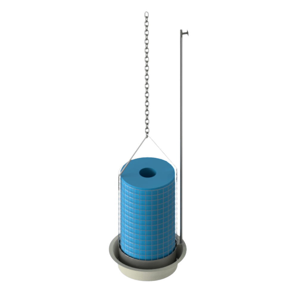

SPEL coalescer units lowered into the separator with the SPEL guide rail system are easily guided into the base unit’s conical moulding to automatically sit correctly.
However, when the separator is full of water, debris or silt accumulated over a period, this could prevent the coalescer unit from re-seating correctly after servicing.
The coalescer unit lifting/locating/locking system provides assurance the coalescer unit is seated correctly and can be locked into position to prevent tampering.
The system is particularly suitable in SPEL Separator + Econoskim® systems where the total contents of the separator are not emptied on servicing.
The system comprises a robust stainless steel lifting and lowering handle that locates on the guide rail system. When the coalescer unit is correctly located in the conical seating in the separator, the handle will align with guide rail top bracket i.e.. the handles slotted holes with the top bracket clip locking groove, see diagram.
When aligned the stainless steel clip can be located through the slots and lock into position on the top bracket.
The stainless steel lifting handle can be extended to suit deep tank inverts and provide easy access for lifting manually or with the SPEL tripod and hoist.
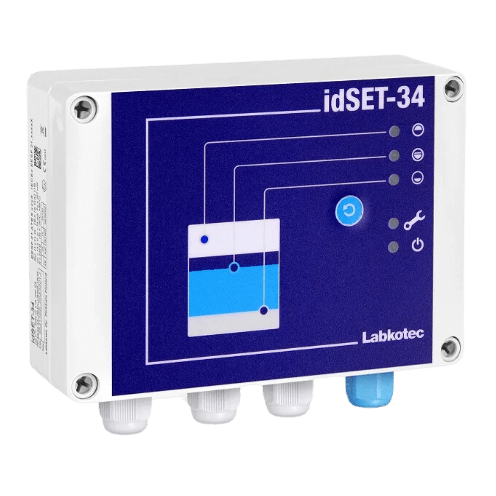
For silt, oil and high level detection, compatible with the below alarm probes.

Available with optional flashing beacon, and GMS/ SMS communication, also compatible with the below alarm probes.

Detects oil and indicates when the treatment system’s oil storage is full. This probe is required in order for a treatment device to comply with BS EN 858.

Monitors the silt layer in the treatment system and indicates when the silt layer has reached its maximum level.
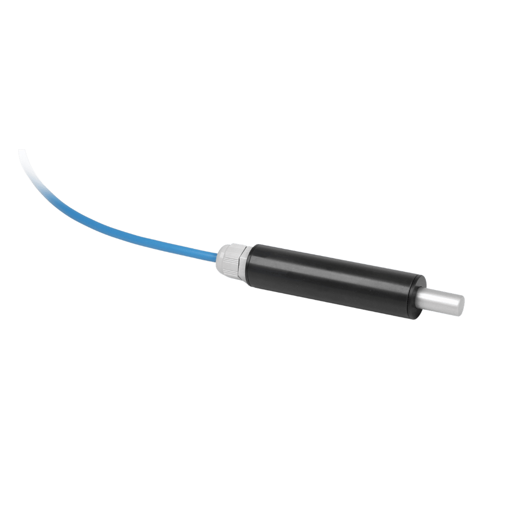
Indicates when the liquid level in the treatment system rises excessively e.g. in an outlet blockage situation.
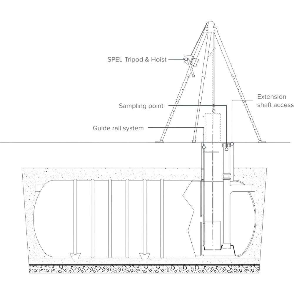
Where surface water run-off has a high silt content the coalescer units can become filled, making them heavy to lift out. In order to facilitate easy withdrawal of coalescer units the SPEL tripod and hoist is recommended.

The SPEL Separator + Econoskim System is a patented system designed to maintain oil separators at peak performance for as long as possible. It does this by skimming the oil from the surface of the separator and transferring it to a separate containment tank for simple collection by a waste oil contractor thus reducing costs and further protecting the environment. For more information, click here.

1. When the SPEL constant monitoring system detects the level of fuel/oil pollutants has reached the pre-determined volume, the skimmers are brought into operation, transferring these pollutants from the SPEL separator to the SPEL Tankstor® containment tank. When the transference of light liquid pollutants has been completed, the system automatically stops the skimming process and re-sets.
2. During the skimming cycle a small amount of water is transferred from the SPEL separator into the SPEL Tankstor® containment tank. In order to maximise the capacity of the SPEL Tankstor® containment tank for pollutants, accumulated water is automatically transferred back to the SPEL separator.

3. The process repeats automatically every time pollutants reach the pre-determined volume. When the SPEL Tankstor® containment tank is 90% full, the SPEL constant monitoring system signals ‘EMPTY NOW’ with an audible and visual alarm.
The Royal Mail DIRFT (Daventry International Rail Freight Terminal) parcel facility is Royal Mail’s largest automated parcel facility in the UK…

The Rugby Gateway Logistics Park is owned by SEGRO and was completed in 2017. It is spread across a vast 120 acre site, with 5 units…

Luton Airport opened in 1938 for use by the Royal Air Force during the Second World War. Commercial and general flights….

Co-op’s new 660,000 sq. ft. regional distribution centre was developed by Tritax Symmetry and constructed by Winvic….
Get personalised, expert assistance with:
Product Selection | Specification Support | Expert Guidance

Fill out the form below with your details and any info you wish to be considered by our team and we will be in touch shortly.
This is the SPEL Puraceptor single chamber model sizing chart. For the difference between single and two chamber models see the explanation below under operation.
Model | Series | Nominal Size (NS) | Catchment Area (m2) | Oil Storage (L) | Silt Capacity (L) | Overall Length* (mm) | Overall Diameter (mm) | Inlet Invert (mm) | Base to Inlet (mm) | Base to Outlet (mm) | Optimum In/Out Pipe Diameter** (mm) | Number of Access Shafts(dia. mm) | ||||
Flow (l/s) | L | A | B | C | 450 | 600 | 750 | 900 | 1200 | |||||||
P004 1C/SC | 200 | 4 | 222 | 40 | 400 | 1,720 | 1,225 | 630 | 1,110 | 1,050 | 160 | – | – | 1 | – | – |
P006 1C/SC | 200 | 6 | 333 | 60 | 600 | 2,310 | 1,225 | 630 | 1,110 | 1,050 | 160 | – | – | 1 | – | – |
P010 1C/SC | 200 | 10 | 556 | 100 | 1,000 | 3,410 | 1,225 | 630 | 1,110 | 1,050 | 160 | – | – | 1 | – | – |
P015 1C/SC | 300 | 15 | 833 | 150 | 1,500 | 3,200 | 1,875 | 350 | 1,800 | 1,740 | 225 | 1 | – | 1 | – | – |
P020 1C/SC | 300 | 20 | 1,111 | 200 | 2,000 | 3,540 | 1,875 | 350 | 1,800 | 1,740 | 225 | – | 1 | 1 | – | – |
FP 1C/SC | 300 | 20 | 1,111 | 200 | 2,000 | 4,290 | 1,875 | 350 | 1,800 | 1,740 | 225 | – | 1 | – | – | |
P030 1C/SC | 300 | 30 | 1,667 | 300 | 3,000 | 4,420 | 1,875 | 390 | 1,760 | 1,700 | 300 | – | 1 | – | 1 | – |
P040 1C/SC | 300 | 40 | 2,222 | 400 | 4,000 | 5,760 | 1,875 | 390 | 1,760 | 1,700 | 300 | – | 1 | – | 1 | – |
P050 1C/SC | 300 | 50 | 2,778 | 500 | 5,000 | 7,060 | 1,875 | 390 | 1,760 | 1,700 | 300 | – | 1 | – | 1 | – |
P065 1C/SC | 400 | 65 | 3,611 | 650 | 6,500 | 4,860 | 2,700 | 425 | 2,625 | 2,525 | 300 | – | 1 | – | 2 | – |
P080 1C/SC | 400 | 80 | 4,444 | 800 | 8,000 | 5,700 | 2,700 | 425 | 2,625 | 2,525 | 300 | – | 1 | – | 2 | – |
P100 1C/SC | 400 | 100 | 5,555 | 1,000 | 10,000 | 7,400 | 2,700 | 475 | 2,575 | 2,475 | 450 | – | 1 | – | 2 | – |
P125 1C/SC | 400 | 125 | 6,944 | 1,250 | 12,500 | 8,580 | 2,700 | 475 | 2,575 | 2,475 | 450 | – | – | 1 | 2 | – |
P150 1C/SC | 400 | 150 | 8,333 | 1,500 | 15,000 | 10,180 | 2,700 | 475 | 2,575 | 2,475 | 450 | – | – | 1 | 2 | – |
P165 1C/SC | 400 | 165 | 9,166 | 1,650 | 16,500 | 11,200 | 2,700 | 500 | 2,550 | 2,450 | 450 | – | 2 | 1 | 1 | – |
P200 1C/SC | 400 | 200 | 11,110 | 2,000 | 20,000 | 13,710 | 2,700 | 660 | 2,390 | 2,290 | 600 | – | 2 | 1 | 1 | – |
P250 1C/SC | 400 | 250 | 13,888 | 2,500 | 25,000 | 16,750 | 2,700 | 660 | 2,390 | 2,290 | 600 | – | 2 | 1 | 2 | – |
P280 1C/SC | 400 | 280 | 15,555 | 2,800 | 28,000 | 18,800 | 2,700 | 660 | 2,390 | 2,290 | 600 | – | 1 | 2 | 2 | – |
P300 1C/SC | 500 | 300 | 16,665 | 3,000 | 30,000 | 12,410 | 3,650 | 805 | 3,070 | 2,970 | 750 | – | 1 | 2 | 2 | – |
P400 1C/SC | 500 | 400 | 22,220 | 4,000 | 40,000 | 15,760 | 3,650 | 805 | 3,070 | 2,970 | 750 | – | 2 | 2 | 2 | – |
P500 1C/SC | 500 | 500 | 27,775 | 5,000 | 50,000 | 20,530 | 3,650 | 955 | 2,920 | 2,820 | 900 | – | 2 | 2 | 1 | 1 |
P500 1C/SC | 600 | 500 | 27,775 | 5,000 | 50,000 | 16,040 | 4,150 | 925 | 3,250 | 3,150 | 900 | – | 2 | 2 | 1 | 1 |
P600 1C/SC | 600 | 600 | 33,330 | 6,000 | 60,000 | 19,080 | 4,150 | 925 | 3,250 | 3,150 | 900 | – | 2 | 2 | – | 2 |
P700 1C/SC | 600 | 700 | 38,888 | 7,000 | 70,000 | 21,460 | 4,150 | 925 | 3,250 | 3,150 | 900 | – | 3 | 2 | 3 | – |
P800 1C/SC | 600 | 800 | 44,440 | 8,000 | 80,000 | 23,020 | 4,150 | 925 | 3,250 | 3,150 | 900 | – | 3 | 2 | 2 | 1 |
All of the above models are available without silt capacity, below are selected models for size comparison. The P1000 model is only available in non silt format. | ||||||||||||||||
P050 1C | 300 | 50 | 2,778 | 500 | – | 5,070 | 1875 | 390 | 1,760 | 1,700 | 300 | – | – | – | 1 | – |
P065 1C | 400 | 65 | 3,611 | 650 | – | 3,710 | 2,700 | 425 | 2,625 | 2,525 | 300 | – | – | 2 | – | |
P100 1C | 400 | 100 | 5,555 | 1,000 | – | 5,250 | 2,700 | 475 | 2,575 | 2,475 | 450 | – | – | 2 | – | |
P125 1C | 400 | 125 | 6,944 | 1,250 | – | 6,090 | 2,700 | 475 | 2,575 | 2,475 | 450 | – | – | – | 2 | – |
P165 1C | 400 | 165 | 9,166 | 1,650 | – | 7,960 | 2,700 | 500 | 2,550 | 2,450 | 450 | – | 2 | 1 | – | |
P250 1C | 400 | 250 | 13,888 | 2,500 | – | 11,830 | 2,700 | 660 | 2,390 | 2,290 | 600 | – | 2 | 2 | – | |
P300 1C | 400 | 300 | 16,665 | 3,000 | – | 14,120 | 2,700 | 660 | 2,390 | 2,290 | 600 | – | 2 | 2 | – | |
P500 1C | 500 | 500 | 27,775 | 5,000 | – | 14,340 | 3,650 | 955 | 2,920 | 2,820 | 900 | – | 2 | 2 | 1 | 1 |
P500 1C | 600 | 500 | 27,775 | 5,000 | – | 11,470 | 4,150 | 925 | 3,250 | 3,150 | 900 | – | 2 | 2 | 1 | 1 |
P700 1C | 600 | 700 | 38,888 | 7,000 | – | 15,880 | 4,150 | 925 | 3,250 | 3,150 | 900 | – | 3 | 2 | 3 | – |
P1000 1C | 600 | 1,000 | 55,550 | 10,000 | – | 21,407 | 4,150 | 925 | 3,250 | 3,150 | 900 | – | 3 | 2 | 1 | 3 |
*Overall length subject to inlet/outlet and orientation.
**SPEL Separators are designed for a maximum flow (NS/NSB) but can be fitted with larger than the recommended maximum connection size IN/OUT or with the addition of adapters providing the maximum flow (NS/NSB) cannot be exceeded or any increase in the operating level in the SPEL Separator to cause the captured pollutants to escape into the vent connections or through access shaft connections. Any overriding of the above criteria could jeopardise performance to the European Standard BS EN 858-1.
Note: Model FP1C/SC is a special Forecourt separator with 7600 litre spillage holding capacity. Click here for more information on Forecourt Separators.
This is the SPEL Puraceptor two chamber model sizing chart. For the difference between single and two chamber models see the explanation below under operation.
Model | Series | Nominal Size (NS) | Catchment Area (m2) | Oil Storage (L) | Silt Capacity (L) | Overall Length* (mm) | Overall Diameter (mm) | Inlet Invert (mm) | Base to Inlet (mm) | Base to Outlet (mm) | Optimum In/Out Pipe Diameter** (mm) | Number of Access Shafts(dia. mm) | ||||
Flow (l/s) | L | A | B | C | 450 | 600 | 750 | 900 | 1200 | |||||||
P006 2C/SC | 200 | 6 | 333 | 60 | 600 | 3,050 | 1,225 | 340 | 1,200 | 1,140 | 160 | – | 1 | 1 | – | – |
P010 2C/SC | 200 | 10 | 556 | 100 | 1,000 | 4,690 | 1,225 | 340 | 1,200 | 1,140 | 160 | – | 1 | 1 | – | – |
P015 2C/SC | 300 | 15 | 833 | 150 | 1,500 | 4,015 | 1,875 | 350 | 1,800 | 1,740 | 225 | – | – | 2 | – | – |
P020 2C/SC | 300 | 20 | 1,111 | 200 | 2,000 | 4,015 | 1,875 | 350 | 1,800 | 1,740 | 225 | – | – | 2 | – | – |
FP 2C/SC*** | 300 | 20 | 1,111 | 200 | 2,000 | 5,500 | 1,875 | 350 | 1,800 | 1,740 | 225 | – | – | 2 | – | – |
P025 2C/SC | 300 | 25 | 1,389 | 250 | 2,500 | 4,290 | 1,875 | 350 | 1,800 | 1,740 | 225 | – | – | 2 | – | – |
P030 2C/SC | 300 | 30 | 1,667 | 300 | 3,000 | 4,420 | 1,875 | 390 | 1,760 | 1,700 | 300 | – | 1 | 2 | – | – |
P035 2C/SC | 300 | 35 | 1,944 | 350 | 3,500 | 5,070 | 1,875 | 390 | 1,760 | 1,700 | 300 | – | 1 | 2 | – | – |
P040 2C/SC | 300 | 40 | 2,222 | 400 | 4,000 | 5,760 | 1,875 | 390 | 1,760 | 1,700 | 300 | – | 1 | 2 | – | – |
P050 2C/SC | 300 | 50 | 2,778 | 500 | 5,000 | 7,060 | 1,875 | 390 | 1,760 | 1,700 | 300 | – | 1 | 2 | – | – |
P065 2C/SC | 300 | 65 | 3,611 | 650 | 6,500 | 9,180 | 1,875 | 390 | 1,760 | 1,700 | 300 | 1 | – | 2 | – | – |
P080 2C/SC | 400 | 80 | 4,444 | 800 | 8,000 | 5,700 | 2,700 | 425 | 2,625 | 2,525 | 300 | – | – | 1 | 1 | – |
P100 2C/SC | 400 | 100 | 5,555 | 1,000 | 10,000 | 7,400 | 2,700 | 475 | 2,575 | 2,475 | 450 | – | – | 1 | 1 | – |
P125 2C/SC | 400 | 125 | 6,944 | 1,250 | 12,500 | 8,580 | 2,700 | 475 | 2,575 | 2,475 | 450 | – | – | 2 | 1 | – |
P150 2C/SC | 400 | 150 | 8,333 | 1,500 | 15,000 | 10,180 | 2,700 | 500 | 2,550 | 2,450 | 450 | – | – | 2 | 1 | – |
P200 2C/SC | 400 | 200 | 11,110 | 2,000 | 20,000 | 13,710 | 2,700 | 660 | 2,390 | 2,290 | 600 | – | 1 | 2 | 1 | – |
P250 2C/SC | 400 | 250 | 13,888 | 2,500 | 25,000 | 16,752 | 2,700 | 660 | 2,390 | 2,290 | 600 | – | 2 | 1 | 2 | – |
P300 2C/SC | 500 | 300 | 16,665 | 3,000 | 30,000 | 12,530 | 3,650 | 675 | 3,200 | 3,100 | 600 | – | 1 | 2 | – | 1 |
P400 2C/SC | 500 | 400 | 22,220 | 4,000 | 40,000 | 15,980 | 3,650 | 675 | 3,200 | 3,100 | 600 | – | 2 | 2 | 2 | – |
P500 2C/SC | 500 | 500 | 27,775 | 5,000 | 50,000 | 20,530 | 3,650 | 955 | 2,920 | 2,820 | 900 | – | 2 | 2 | 1 | 1 |
P500 2C/SC | 600 | 500 | 27,775 | 5,000 | 50,000 | 16,260 | 4,150 | 925 | 3,250 | 3,150 | 900 | – | 2 | 1 | 1 | 1 |
P600 2C/SC | 600 | 600 | 33,330 | 6,000 | 60,000 | 19,080 | 4,150 | 925 | 3,250 | 3,150 | 900 | – | 2 | 2 | 3 | – |
P700 2C/SC | 600 | 700 | 38,888 | 7,000 | 70,000 | 22,270 | 4,150 | 925 | 3,250 | 3,150 | 900 | – | 3 | 2 | 3 | – |
P800 2C/SC | 600 | 800 | 44,440 | 8,000 | 80,000 | 23,020 | 4,150 | 925 | 3,250 | 3,150 | 900 | – | 3 | 2 | 2 | 1 |
P900 2C/SC | 600 | 900 | 50,000 | 9,000 | 90,000 | 24,658 | 4,150 | 925 | 3,250 | 3,150 | 900 | – | 3 | 2 | 1 | 2 |
*Overall length subject to inlet/outlet and orientation.
**SPEL Separators are designed for a maximum flow (NS/NSB) but can be fitted with larger than the recommended maximum connection size IN/OUT or with the addition of adapters providing the maximum flow (NS/NSB) cannot be exceeded or any increase in the operating level in the SPEL Separator to cause the captured pollutants to escape into the vent connections or through access shaft connections. Any overriding of the above criteria could jeopardise performance to the European Standard BS EN 858-1.
Note: Model FP2C/SC is a special Forecourt separator with 7600 litre spillage holding capacity. Click here for more information on Forecourt Separators.
| Model | Series | Meals per Day* | NSG | Tank Length (mm) | Internal Diameter (mm) | Overall Capacity (L) | Grease Capacity (L) | Inlet Invert (m) | Base to Inlet (mm) | Base to Outlet(mm) | Optimum In/Out Pipe Diameter** (mm) | Number of Access Shafts (dia. mm) |
|---|---|---|---|---|---|---|---|---|---|---|---|---|
| L | A | B | C | 600 | ||||||||
| GS200/2000 | 200 | 400 | 4 | 2,040 | 1,200 | 2,000 | 160 | 505 | 1,020 | 970 | 160 | 2 |
| GS200/3000 | 200 | 600 | 6 | 2,930 | 1,200 | 3,000 | 240 | 505 | 1,020 | 970 | 160 | 2 |
| GS200/4000 | 200 | 900 | 9 | 3,810 | 1,200 | 4,000 | 360 | 505 | 1,020 | 970 | 160 | 2 |
| GS200/5000 | 200 | 1100 | 11 | 4,700 | 1,200 | 5,000 | 440 | 505 | 1,020 | 970 | 160 | 2 |
| GS200/6000 | 200 | 1400 | 14 | 5,578 | 1,200 | 6,000 | 560 | 505 | 1,020 | 970 | 160 | 2 |
| GS300/5860 | 300 | 1400 | 14 | 2,690 | 1,800 | 5,860 | 560 | 538 | 1,570 | 1,520 | 160 | 2 |
| GS300/9270 | 300 | 1800 | 18 | 4,015 | 1,800 | 9,270 | 720 | 538 | 1,570 | 1,520 | 160 | 2 |
| GS300/18200 | 300 | 4000 | 40 | 7,620 | 1,800 | 18,200 | 1600 | 538 | 1,570 | 1,520 | 160 | 2 |
| Model | Series | Max. Flow* | Silt Capacity (L) | Overall Length* | Internal Diameter (mm) | Opt In/Out Pipe Diameter (mm) | Number of Access Shafts (dia. mm) | Inlet Invert (mm) |
|---|---|---|---|---|---|---|---|---|
| Flow (l/s) | L | 600 | A | |||||
| WDS 200/1000 | 200 | 1.1 | 250 | 1.17 | 1,200 | 160mm | 1 | – |
| WDS 200/2000 | 200 | 2.2 | 500 | 2.05 | 1,200 | 160mm | 1 | – |
| WDS 200/3000 | 200 | 3.3 | 700 | 2.93 | 1,200 | 160mm | 1 | – |
| WDS 200/4000 | 200 | 4.5 | 1,000 | 3.82 | 1,200 | 160mm | 1 | – |
| WDS 200/5000 | 200 | 5.6 | 1,250 | 4.7 | 1,200 | 160mm | 1 | – |
| WDS 200/6000 | 200 | 6.7 | 1,500 | 5.59 | 1,200 | 160mm | 1 | – |
| WDS 200/7000 | 200 | 7.8 | 1,750 | 6.48 | 1,200 | 160mm | 1 | – |
| WDS 200/8000 | 200 | 9 | 2,000 | 7.36 | 1,200 | 160mm | 1 | – |
| WDS 200/9000 | 200 | 10 | 2,250 | 8.25 | 1,200 | 160mm | 1 | – |
| WDS 200/10,000 | 200 | 11 | 2,500 | 9.13 | 1,200 | 160mm | 1 | – |
| WDS 300/4000 | 300 | 5 | 1,000 | 1.95 | 1,800 | 160mm | 1 | – |
| WDS 300/6000 | 300 | 7 | 1,500 | 2.76 | 1,800 | 160mm | 1 | – |
| WDS 300/8000 | 300 | 9 | 2,000 | 3.54 | 1,800 | 160mm | 1 | – |
| WDS 300/10,000 | 300 | 12 | 2,500 | 4.29 | 1,800 | 160mm | 1 | – |
| Model | Series | Nominal Size (NB) | Catchment Area (M2) | Oil Storage (L) | Silt Capacity (L) | Overall Length* (mm) | Overall Diameter (mm) | Inlet Invert (mm) | Base to Inlet (mm) | Base to Outlet (mm) | Optimum In/Out pipe Diameter** (mm) | Number of Access Shafts (dia. mm) | ||||
|---|---|---|---|---|---|---|---|---|---|---|---|---|---|---|---|---|
| Flow (l/s) | A | B | C | 450 | 600 | 750 | ||||||||||
| FR004 SC | 200 | 4 | 222 | 40 | 400 | 1,720 | 1225 | 630 | 1,110 | 1,050 | 160 | 1 | ||||
| FR006 SC | 200 | 6 | 333 | 60 | 600 | 2,270 | 1,225 | 630 | 1,110 | 1,050 | 160 | 1 | ||||
| FR010 SC | 200 | 10 | 556 | 100 | 1,000 | 3,410 | 1,225 | 630 | 1,110 | 1,050 | 160 | 1 | ||||
| FR015 SC | 300 | 15 | 833 | 150 | 1,500 | 2,760 | 1,875 | 350 | 1,800 | 1,740 | 225 | 1 | ||||
| FR020 SC | 300 | 20 | 1,111 | 200 | 2,000 | 3,200 | 1,875 | 350 | 1,800 | 1,740 | 225 | 1 | ||||
| FS2 SC | 300 | 20 | 1,111 | 200 | 2,000 | 4,290 | 1,875 | 350 | 1,800 | 1,740 | 225 | 1 | ||||
| FR030 SC | 300 | 30 | 1,667 | 300 | 3,000 | 4,420 | 1,875 | 390 | 1,760 | 1,700 | 300 | 1 | ||||
| FR040 SC | 300 | 40 | 2,222 | 400 | 4,000 | 5,760 | 1,875 | 390 | 1,760 | 1,700 | 300 | 1 | ||||
| FR050 SC | 300 | 50 | 2,778 | 500 | 5,000 | 7,060 | 1,875 | 390 | 1,760 | 1,700 | 300 | 1 | ||||
| FR065 SC | 400 | 65 | 3,611 | 650 | 6,500 | 4,810 | 2,700 | 425 | 2,625 | 2,525 | 300 | 1 | 1 | |||
| FR080 SC | 400 | 80 | 4,444 | 800 | 8,000 | 5,700 | 2,700 | 425 | 2,625 | 2,525 | 300 | 1 | 1 | |||
| FR100 SC | 400 | 100 | 5,555 | 1,000 | 10,000 | 7,400 | 2,700 | 475 | 2,575 | 2,475 | 450 | 1 | 1 | |||
| FR125 SC | 400 | 125 | 6,944 | 1,250 | 12,500 | 8,580 | 2,700 | 475 | 2,575 | 2,475 | 450 | 1 | 1 | |||
| FR150 SC | 400 | 150 | 8,333 | 1,500 | 15,000 | 10,180 | 2,700 | 475 | 2,575 | 2,475 | 450 | 1 | 1 | |||
| FR165 SC | 400 | 165 | 9,166 | 1,650 | 16,500 | 11,200 | 2,700 | 500 | 2,550 | 2,450 | 450 | 2 | ||||
| FR200 SC | 400 | 200 | 11,110 | 2,000 | 20,000 | 13,710 | 2,700 | 660 | 2,390 | 2,290 | 600 | 2 | ||||
| FR250 SC | 400 | 250 | 13,888 | 2,500 | 25,000 | 16,750 | 2,700 | 660 | 2,390 | 2,290 | 600 | 2 | ||||
| Model | Series | Nominal Size (NB) | Catchment Area (M2) | Oil Storage (L) | Silt Capacity (L) | Overall Length* (mm) | Overall Diameter (mm) | Inlet Invert (mm) | Base to Inlet (mm) | Base to Outlet (mm) | Optimum In/Out pipe Diameter** (mm) | Number of Access Shafts (dia. mm) | ||||
|---|---|---|---|---|---|---|---|---|---|---|---|---|---|---|---|---|
| Flow (l/s) | A | B | C | 450 | 600 | 750 | ||||||||||
| FR040 | 300 | 40 | 2,222 | 400 | 4,020 | 1,875 | 390 | 1,760 | 1,700 | 300 | 1 | |||||
| FR050 | 300 | 50 | 2,778 | 500 | 5,070 | 1,875 | 390 | 1,760 | 1,700 | 300 | 1 | |||||
| FR065 | 400 | 65 | 3,611 | 650 | 3,710 | 2,700 | 425 | 2,625 | 2,525 | 300 | 1 | 1 | ||||
| FR080 | 400 | 80 | 4,444 | 800 | 4,400 | 2,700 | 425 | 2,625 | 2,525 | 300 | 1 | 1 | ||||
| FR100 | 400 | 100 | 5,555 | 1000 | 5,250 | 2,700 | 475 | 2,575 | 2,475 | 450 | 1 | 1 | ||||
| FR125 | 400 | 125 | 6,944 | 1250 | 6,090 | 2,700 | 475 | 2,575 | 2,475 | 450 | 1 | 1 | ||||
| FRI50 | 400 | 150 | 8,333 | 1500 | 7,400 | 2,700 | 475 | 2,575 | 2,475 | 450 | 1 | 1 | ||||
| FR165 | 400 | 165 | 9,166 | 1650 | 7,960 | 2,700 | 500 | 2,550 | 2,450 | 450 | 2 | |||||
| FR200 | 400 | 200 | 11,110 | 2000 | 9,600 | 2,700 | 660 | 2,390 | 2,290 | 600 | 2 | |||||
| FR250 | 400 | 250 | 13,888 | 2500 | 11,830 | 2,700 | 660 | 2,390 | 2,290 | 600 | 2 | |||||
| FR300 | 400 | 300 | 16,665 | 3000 | 14,120 | 2,700 | 660 | 2,390 | 2,290 | 600 | 2 | |||||
| FR400 | 500 | 400 | 222,222 | 4,000 | optional | * | 3,650 | – | 3 | – | ||||||
*Overall length subject to inlet/outlet size and orientation
**SPEL Separators are designed for a maximum flow (NS/NSB) but can be fitted with larger than the recommended maximum connection size IN/OUT or with the addition of adapters providing the maximum flow (NS/NSB) cannot be exceeded or any increase in the operating level in the SPEL Separator to cause the captured pollutants to escape into the vent connections or through access shaft connections. Any overriding of the above criteria could jeopardise performance to the European Standard BS EN 858-1.
Note: Model FS2SC is a special forecourt unit with 7600 litre spillage holding capacity.
Model | Series | Nominal Size (NS) | Catchment Area (m2) | Oil Storage (L) | Silt Capacity (L) | Overall Length (mm) | Inlet Invert (mm) | Base to Inlet (mm) | Base to Outlet (mm) | Optimum Inlet dia.** (mm) |
Flow (l/s) | L | |||||||||
P006 2C/SC/M | 300 | 6 | 333 | 60 | 600 | 3,200 | 540 | 1,610 | 1,550 | 160 |
P010 2C/SC/M | 300 | 10 | 556 | 100 | 1,000 | 5,070 | 540 | 1,610 | 1,550 | 160 |
P015 2C/SC/M | 300 | 15 | 833 | 150 | 1,500 | 6,570 | 550 | 1,600 | 1,500 | 225 |
P020 2C/SC/M | 400 | 20 | 1,111 | 200 | 2,000 | 5,250 | 625 | 2,425 | 2,325 | 225 |
P025 2C/SC/M | 400 | 25 | 1,389 | 250 | 2,500 | 6,170 | 625 | 2,425 | 2,325 | 225 |
P030 2C/SC/M | 400 | 30 | 1,667 | 300 | 3,000 | 7,400 | 625 | 2,425 | 2,325 | 300 |
P040 2C/SC/M | 400 | 40 | 2,222 | 400 | 4,000 | 9,930 | For details, please contact our Technical Sales Team | 300 | ||
P060 2C/SC/M | 400 | 60 | 3,333 | 600 | 6,000 | 13,710 | For details, please contact our Technical Sales Team | 300 | ||
P080 2C/SC/M | 500 | 80 | 4,444 | 800 | 8,000 | 10,040 | For details, please contact our Technical Sales Team | 300 | ||
P100 2C/SC/M | 500 | 100 | 5,555 | 1,000 | 10,000 | 12,530 | For details, please contact our Technical Sales Team | 450 | ||
| Model | Series | Nominal Size (NS) | Catchment Area (m2) | Oil Storage (L) | Silt Capacity (L) | Overall Length* (mm) | Overall Diameter (mm) | Inlet Invert (mm) | Base to Inlet (mm) | Base to Outlet (mm) | Optimum In/Out Pipe Diameter** (mm) | Number of Access Shafts (dia. mm) | ||||||
|---|---|---|---|---|---|---|---|---|---|---|---|---|---|---|---|---|---|---|
| Flow (l/s) | L | A | B | C | 450 | 750 | 900 | 1200 | ||||||||||
| P006 2C/SC/NG | 200 | 6 | 333 | 60 | 600 | 3,050 | 1225 | 427 | 1,110 | 1,050 | 160 | – | 1 | 1 | – | |||
| P010 2C/SC/NG | 200 | 10 | 556 | 100 | 1,000 | 4,700 | 1,225 | 427 | 1,110 | 1,050 | 160 | – | 3 | – | – | |||
| P015 2C/SC/NG | 300 | 15 | 833 | 150 | 1,500 | 4,020 | 1,875 | 540 | 1,610 | 1,550 | 225 | – | 3 | – | – | |||
| P020 2C/SC/NG | 300 | 20 | 1,111 | 200 | 2,000 | 4,020 | 1,875 | 540 | 1,610 | 1,550 | 225 | – | 3 | – | – | |||
| P025 2C/SC/NG | 300 | 25 | 1,389 | 250 | 2,500 | 4,290 | 1,875 | 540 | 1,610 | 1,550 | 225 | – | 3 | – | – | |||
| P030 2C/SC/NG | 300 | 30 | 1,667 | 300 | 3,000 | 5,070 | 1,875 | 550 | 1,600 | 1,500 | 300 | – | 2 | 1 | – | |||
| P040 2C/SC/NG | 300 | 40 | 2,222 | 400 | 4,000 | 6,570 | 1,875 | 550 | 1,600 | 1,500 | 300 | – | 2 | 1 | – | |||
| P050 2C/SC/NG | 300 | 50 | 2,778 | 500 | 5,000 | 8,260 | 1,875 | 550 | 1,600 | 1,500 | 300 | – | 2 | 1 | – | |||
| P065 2C/SC/NG | 300 | 65 | 3,611 | 650 | 6,500 | 10,220 | 1,875 | 550 | 1,600 | 1,500 | 300 | 1 | 2 | 1 | – | |||
| P065 2C/SC/NG | 400 | 65 | 3,611 | 650 | 6,500 | 5,470 | 2,700 | 665 | 2,385 | 2,285 | 300 | 1 | 1 | 1 | – | |||
| P080 2C/SC/NG | 400 | 80 | 4,444 | 800 | 8,000 | 6,170 | 2,700 | 665 | 2,385 | 2,285 | 300 | 1 | 1 | 1 | – | |||
| P100 2C/SC/NG | 400 | 100 | 5,555 | 1,000 | 10,000 | 7400 | 2,700 | 665 | 2385 | 2285 | 450 | 1 | 1 | 1 | – | |||
| P125 2C/SC/NG | 400 | 125 | 6,944 | 1,250 | 12,500 | 9,600 | 2,700 | 765 | 2,285 | 2,185 | 450 | 1 | 2 | – | 1 | |||
| P150 2C/SC/NG | 400 | 150 | 8,333 | 1,500 | 15,000 | 11,200 | 2,700 | 790 | 2,280 | 2,180 | 450 | 1 | 2 | – | 1 | |||
| P200 2C/SC/NG | 400 | 200 | 11,110 | 2,000 | 20,000 | 16,400 | 2,700 | 940 | 2,130 | 2,030 | 600 | 2 | 2 | – | 1 | |||
| P300 2C/SC/NG | 500 | 300 | 16,665 | 3,000 | 30,000 | 12,530 | 3,650 | 875 | 3,000 | 2,900 | 600 | 2 | 2 | – | 1 | |||
| P400 2C/SC/NG | 500 | 400 | 22,220 | 4,000 | 40,000 | 16,330 | 3,650 | 875 | 3,000 | 2,900 | 600 | 3 | 2 | 2 | – | |||
| Model | Series | Nominal Size (NS) | Catchment Area (m2) | Oil Storage (L) | Silt Capacity (L) | Overall Length* (mm) | Overall Diameter (mm) | Inlet Invert (mm) | Base to Inlet (mm) | Base to Outlet (mm) | Optimum In/Out Pipe Diameter* (mm) | Number of Access Shafts (dia. mm) | ||||
|---|---|---|---|---|---|---|---|---|---|---|---|---|---|---|---|---|
| Flow (l/s) | L | A | B | C | 750 | 900 | 1200 | |||||||||
| FP 1C/SCClass 1 Forecourt SeparatorSingle Chamber with Silt Capture | 300 | 20 | 1,111 | 200 | 2,000 | 4,290 | 1,875 | 350 | 1,800 | 1,740 | 225 | 1 | – | – | ||
| FP 2C/SCClass 1 Forecourt SeparatorTwo Chamber with Silt Capture | 300 | 20 | 1,111 | 200 | 2,000 | 5,500 | 1,875 | 350 | 1,800 | 1,740 | 225 | 2 | – | – | ||
| FS2 SCClass 2 Forecourt SeparatorSingle Chamber with Silt Capture | 300 | 20 | 1,111 | 200 | 2,000 | 4,290 | 1,875 | 350 | 1,800 | 1,740 | 225 | – | – | 1 | ||
Model | Series | Nominal Size (NS) | Catchment Area (m2) | Oil Storage (L) | Silt Capacity (L) | Overall Length* (mm) | Overall Diameter (mm) | Inlet Invert (mm) | Base to Inlet (mm) | Base to Outlet (mm) | Optimum In/Out Pipe Diameter** (mm) | Number of Access Shafts(dia. mm) | ||||
Flow (l/s) | L | A | B | C | 450 | 600 | 750 | 900 | 1200 | |||||||
P006 2C/SC | 200 | 6 | 333 | 60 | 600 | 3,050 | 1,225 | 340 | 1,200 | 1,140 | 160 | – | 1 | 1 | – | – |
P010 2C/SC | 200 | 10 | 556 | 100 | 1,000 | 4,690 | 1,225 | 340 | 1,200 | 1,140 | 160 | – | 1 | 1 | – | – |
P015 2C/SC | 300 | 15 | 833 | 150 | 1,500 | 4,015 | 1,875 | 350 | 1,800 | 1,740 | 225 | – | – | 2 | – | – |
P020 2C/SC | 300 | 20 | 1,111 | 200 | 2,000 | 4,015 | 1,875 | 350 | 1,800 | 1,740 | 225 | – | – | 2 | – | – |
FP 2C/SC*** | 300 | 20 | 1,111 | 200 | 2,000 | 5,500 | 1,875 | 350 | 1,800 | 1,740 | 225 | – | – | 2 | – | – |
P025 2C/SC | 300 | 25 | 1,389 | 250 | 2,500 | 4,290 | 1,875 | 350 | 1,800 | 1,740 | 225 | – | – | 2 | – | – |
P030 2C/SC | 300 | 30 | 1,667 | 300 | 3,000 | 4,420 | 1,875 | 390 | 1,760 | 1,700 | 300 | – | 1 | 2 | – | – |
P035 2C/SC | 300 | 35 | 1,944 | 350 | 3,500 | 5,070 | 1,875 | 390 | 1,760 | 1,700 | 300 | – | 1 | 2 | – | – |
P040 2C/SC | 300 | 40 | 2,222 | 400 | 4,000 | 5,760 | 1,875 | 390 | 1,760 | 1,700 | 300 | – | 1 | 2 | – | – |
P050 2C/SC | 300 | 50 | 2,778 | 500 | 5,000 | 7,060 | 1,875 | 390 | 1,760 | 1,700 | 300 | – | 1 | 2 | – | – |
P065 2C/SC | 300 | 65 | 3,611 | 650 | 6,500 | 9,180 | 1,875 | 390 | 1,760 | 1,700 | 300 | 1 | – | 2 | – | – |
P080 2C/SC | 400 | 80 | 4,444 | 800 | 8,000 | 5,700 | 2,700 | 425 | 2,625 | 2,525 | 300 | – | – | 1 | 1 | – |
P100 2C/SC | 400 | 100 | 5,555 | 1,000 | 10,000 | 7,400 | 2,700 | 475 | 2,575 | 2,475 | 450 | – | – | 1 | 1 | – |
P125 2C/SC | 400 | 125 | 6,944 | 1,250 | 12,500 | 8,580 | 2,700 | 475 | 2,575 | 2,475 | 450 | – | – | 2 | 1 | – |
P150 2C/SC | 400 | 150 | 8,333 | 1,500 | 15,000 | 10,180 | 2,700 | 500 | 2,550 | 2,450 | 450 | – | – | 2 | 1 | – |
P200 2C/SC | 400 | 200 | 11,110 | 2,000 | 20,000 | 13,710 | 2,700 | 660 | 2,390 | 2,290 | 600 | – | 1 | 2 | 1 | – |
P250 2C/SC | 400 | 250 | 13,888 | 2,500 | 25,000 | 16,752 | 2,700 | 660 | 2,390 | 2,290 | 600 | – | 2 | 1 | 2 | – |
P300 2C/SC | 500 | 300 | 16,665 | 3,000 | 30,000 | 12,530 | 3,650 | 675 | 3,200 | 3,100 | 600 | – | 1 | 2 | – | 1 |
P400 2C/SC | 500 | 400 | 22,220 | 4,000 | 40,000 | 15,980 | 3,650 | 675 | 3,200 | 3,100 | 600 | – | 2 | 2 | 2 | – |
P500 2C/SC | 500 | 500 | 27,775 | 5,000 | 50,000 | 20,530 | 3,650 | 955 | 2,920 | 2,820 | 900 | – | 2 | 2 | 1 | 1 |
P500 2C/SC | 600 | 500 | 27,775 | 5,000 | 50,000 | 16,260 | 4,150 | 925 | 3,250 | 3,150 | 900 | – | 2 | 1 | 1 | 1 |
P600 2C/SC | 600 | 600 | 33,330 | 6,000 | 60,000 | 19,080 | 4,150 | 925 | 3,250 | 3,150 | 900 | – | 2 | 2 | 3 | – |
P700 2C/SC | 600 | 700 | 38,888 | 7,000 | 70,000 | 22,270 | 4,150 | 925 | 3,250 | 3,150 | 900 | – | 3 | 2 | 3 | – |
P800 2C/SC | 600 | 800 | 44,440 | 8,000 | 80,000 | 23,020 | 4,150 | 925 | 3,250 | 3,150 | 900 | – | 3 | 2 | 2 | 1 |
P900 2C/SC | 600 | 900 | 50,000 | 9,000 | 90,000 | 24,658 | 4,150 | 925 | 3,250 | 3,150 | 900 | – | 3 | 2 | 1 | 2 |
Model | Series | Nominal Size (NS) | Catchment Area (m2) | Oil Storage (L) | Silt Capacity (L) | Overall Length* (mm) | Overall Diameter (mm) | Inlet Invert (mm) | Base to Inlet (mm) | Base to Outlet (mm) | Optimum In/Out Pipe Diameter** (mm) | Number of Access Shafts(dia. mm) | ||||
Flow (l/s) | L | A | B | C | 450 | 600 | 750 | 900 | 1200 | |||||||
P004 1C/SC | 200 | 4 | 222 | 40 | 400 | 1,720 | 1,225 | 630 | 1,110 | 1,050 | 160 | – | – | 1 | – | – |
P006 1C/SC | 200 | 6 | 333 | 60 | 600 | 2,310 | 1,225 | 630 | 1,110 | 1,050 | 160 | – | – | 1 | – | – |
P010 1C/SC | 200 | 10 | 556 | 100 | 1,000 | 3,410 | 1,225 | 630 | 1,110 | 1,050 | 160 | – | – | 1 | – | – |
P015 1C/SC | 300 | 15 | 833 | 150 | 1,500 | 3,200 | 1,875 | 350 | 1,800 | 1,740 | 225 | 1 | – | 1 | – | – |
P020 1C/SC | 300 | 20 | 1,111 | 200 | 2,000 | 3,540 | 1,875 | 350 | 1,800 | 1,740 | 225 | – | 1 | 1 | – | – |
FP 1C/SC | 300 | 20 | 1,111 | 200 | 2,000 | 4,290 | 1,875 | 350 | 1,800 | 1,740 | 225 | – | 1 | – | – | |
P030 1C/SC | 300 | 30 | 1,667 | 300 | 3,000 | 4,420 | 1,875 | 390 | 1,760 | 1,700 | 300 | – | 1 | – | 1 | – |
P040 1C/SC | 300 | 40 | 2,222 | 400 | 4,000 | 5,760 | 1,875 | 390 | 1,760 | 1,700 | 300 | – | 1 | – | 1 | – |
P050 1C/SC | 300 | 50 | 2,778 | 500 | 5,000 | 7,060 | 1,875 | 390 | 1,760 | 1,700 | 300 | – | 1 | – | 1 | – |
P065 1C/SC | 400 | 65 | 3,611 | 650 | 6,500 | 4,860 | 2,700 | 425 | 2,625 | 2,525 | 300 | – | 1 | – | 2 | – |
P080 1C/SC | 400 | 80 | 4,444 | 800 | 8,000 | 5,700 | 2,700 | 425 | 2,625 | 2,525 | 300 | – | 1 | – | 2 | – |
P100 1C/SC | 400 | 100 | 5,555 | 1,000 | 10,000 | 7,400 | 2,700 | 475 | 2,575 | 2,475 | 450 | – | 1 | – | 2 | – |
P125 1C/SC | 400 | 125 | 6,944 | 1,250 | 12,500 | 8,580 | 2,700 | 475 | 2,575 | 2,475 | 450 | – | – | 1 | 2 | – |
P150 1C/SC | 400 | 150 | 8,333 | 1,500 | 15,000 | 10,180 | 2,700 | 475 | 2,575 | 2,475 | 450 | – | – | 1 | 2 | – |
P165 1C/SC | 400 | 165 | 9,166 | 1,650 | 16,500 | 11,200 | 2,700 | 500 | 2,550 | 2,450 | 450 | – | 2 | 1 | 1 | – |
P200 1C/SC | 400 | 200 | 11,110 | 2,000 | 20,000 | 13,710 | 2,700 | 660 | 2,390 | 2,290 | 600 | – | 2 | 1 | 1 | – |
P250 1C/SC | 400 | 250 | 13,888 | 2,500 | 25,000 | 16,750 | 2,700 | 660 | 2,390 | 2,290 | 600 | – | 2 | 1 | 2 | – |
P280 1C/SC | 400 | 280 | 15,555 | 2,800 | 28,000 | 18,800 | 2,700 | 660 | 2,390 | 2,290 | 600 | – | 1 | 2 | 2 | – |
P300 1C/SC | 500 | 300 | 16,665 | 3,000 | 30,000 | 12,410 | 3,650 | 805 | 3,070 | 2,970 | 750 | – | 1 | 2 | 2 | – |
P400 1C/SC | 500 | 400 | 22,220 | 4,000 | 40,000 | 15,760 | 3,650 | 805 | 3,070 | 2,970 | 750 | – | 2 | 2 | 2 | – |
P500 1C/SC | 500 | 500 | 27,775 | 5,000 | 50,000 | 20,530 | 3,650 | 955 | 2,920 | 2,820 | 900 | – | 2 | 2 | 1 | 1 |
P500 1C/SC | 600 | 500 | 27,775 | 5,000 | 50,000 | 16,040 | 4,150 | 925 | 3,250 | 3,150 | 900 | – | 2 | 2 | 1 | 1 |
P600 1C/SC | 600 | 600 | 33,330 | 6,000 | 60,000 | 19,080 | 4,150 | 925 | 3,250 | 3,150 | 900 | – | 2 | 2 | – | 2 |
P700 1C/SC | 600 | 700 | 38,888 | 7,000 | 70,000 | 21,460 | 4,150 | 925 | 3,250 | 3,150 | 900 | – | 3 | 2 | 3 | – |
P800 1C/SC | 600 | 800 | 44,440 | 8,000 | 80,000 | 23,020 | 4,150 | 925 | 3,250 | 3,150 | 900 | – | 3 | 2 | 2 | 1 |
All of the above models are available without silt capacity, below are selected models for size comparison. The P1000 model is only available in non silt format. | ||||||||||||||||
P050 1C | 300 | 50 | 2,778 | 500 | – | 5,070 | 1875 | 390 | 1,760 | 1,700 | 300 | – | – | – | 1 | – |
P065 1C | 400 | 65 | 3,611 | 650 | – | 3,710 | 2,700 | 425 | 2,625 | 2,525 | 300 | – | – | 2 | – | |
P100 1C | 400 | 100 | 5,555 | 1,000 | – | 5,250 | 2,700 | 475 | 2,575 | 2,475 | 450 | – | – | 2 | – | |
P125 1C | 400 | 125 | 6,944 | 1,250 | – | 6,090 | 2,700 | 475 | 2,575 | 2,475 | 450 | – | – | – | 2 | – |
P165 1C | 400 | 165 | 9,166 | 1,650 | – | 7,960 | 2,700 | 500 | 2,550 | 2,450 | 450 | – | 2 | 1 | – | |
P250 1C | 400 | 250 | 13,888 | 2,500 | – | 11,830 | 2,700 | 660 | 2,390 | 2,290 | 600 | – | 2 | 2 | – | |
P300 1C | 400 | 300 | 16,665 | 3,000 | – | 14,120 | 2,700 | 660 | 2,390 | 2,290 | 600 | – | 2 | 2 | – | |
P500 1C | 500 | 500 | 27,775 | 5,000 | – | 14,340 | 3,650 | 955 | 2,920 | 2,820 | 900 | – | 2 | 2 | 1 | 1 |
P500 1C | 600 | 500 | 27,775 | 5,000 | – | 11,470 | 4,150 | 925 | 3,250 | 3,150 | 900 | – | 2 | 2 | 1 | 1 |
P700 1C | 600 | 700 | 38,888 | 7,000 | – | 15,880 | 4,150 | 925 | 3,250 | 3,150 | 900 | – | 3 | 2 | 3 | – |
P1000 1C | 600 | 1,000 | 55,550 | 10,000 | – | 21,407 | 4,150 | 925 | 3,250 | 3,150 | 900 | – | 3 | 2 | 1 | 3 |
| Model | Nominal Size (NSB) | Peak Flow (l/s) | Catchment Area (m2) | Oil Storage (L) | Silt Storage (L) | Length (mm) | Internal Diameter (mm) | Inlet Invert (mm) | Base to Inlet (mm) | Base to Outlet (mm) | Optimum in/out Pipe Diameter (mm) for Orientation* | Number of Access Shafts A-C** Diameter (mm) | ||||||
|---|---|---|---|---|---|---|---|---|---|---|---|---|---|---|---|---|---|---|
| Flow (l/s) | NSB x 15 | NSB x 100 | L | W | A | B | C | 450 | 600 | 750* | 900 | |||||||
| 103 C1/SC | 3 | 30 | 1,667 | 45 | 300 | 1,550 | 1,300 | 500 | 1,015 | 965 | 160 | – | – | – | – | |||
| 204 C1/SC | 4 | 40 | 2,222 | 60 | 400 | 1,860 | 1,200 | 550 | 1,350 | 1,300 | 300 | – | – | 1 | – | |||
| 206 C1/SC | 6 | 60 | 3,333 | 90 | 600 | 2,120 | 1,200 | 550 | 1,350 | 1,300 | 300 | – | – | 1 | – | |||
| 208 C1/SC | 8 | 80 | 4,444 | 120 | 800 | 2,270 | 1,200 | 550 | 1,350 | 1,300 | 300 | – | – | 1 | – | |||
| 210 C1/SC | 10 | 100 | 5,556 | 150 | 1,000 | 2,920 | 1,200 | 550 | 1,350 | 1,300 | 300 | – | – | 1 | – | |||
| 212 C1/SC | 12 | 120 | 6,667 | 180 | 1,200 | 3,570 | 1,200 | 560 | 1,350 | 1,300 | 300 | – | – | 1 | – | |||
| 215 C1/SC | 15 | 150 | 8,333 | 225 | 1,500 | 4,237 | 1,200 | 560 | 1,350 | 1,300 | 300 | – | – | 1 | – | |||
| 320 C1/SC | 20 | 200 | 11,111 | 300 | 2,000 | 3,200 | 1,800 | 700 | 1,450 | 1,350 | 450 | – | 2 | – | – | |||
| 325 C1/SC | 25 | 250 | 13,889 | 375 | 2,500 | 3,540 | 1,800 | 700 | 1,450 | 1,350 | 450 | – | 2 | – | – | |||
| 330 C1/SC | 30 | 300 | 16,667 | 450 | 3,000 | 4,420 | 1,800 | 700 | 1,450 | 1,350 | 450 | – | – | 1 | 1 | |||
| 340 C1/SC | 40 | 400 | 22,222 | 600 | 4,000 | 5,760 | 1,800 | 740 | 1,410 | 1,310 | 450 | – | 1 | 1 | – | |||
| 345 C1/SC | 45 | 450 | 25,000 | 675 | 4,500 | 6,570 | 1,800 | 740 | 1,410 | 1,310 | 450 | – | 1 | 1 | – | |||
| 350 C1/SC | 50 | 500 | 27,778 | 750 | 5,000 | 7,060 | 1,800 | 740 | 1,410 | 1,310 | 450 | – | 1 | 1 | – | |||
| 460 C1/SC | 60 | 600 | 33,333 | 900 | 6,000 | 4,400 | 2,600 | 950 | 2,100 | 2,000 | 600 | – | – | 1 | 1 | |||
| 470 C1/SC | 70 | 700 | 38,889 | 1,050 | 7,000 | 5,250 | 2,600 | 950 | 2,100 | 2,000 | 600 | – | – | 1 | 1 | |||
| 480 C1/SC | 80 | 800 | 44,444 | 1,200 | 8,000 | 6,170 | 2,600 | 950 | 2,100 | 2,000 | 600 | – | – | 1 | 1 | |||
| 4100 C1/SC | 100 | 1,000 | 55,556 | 1,500 | 10,000 | 7,400 | 2,600 | 1,100 | 1,950 | 1,850 | 750 | – | – | 1 | 1 | |||
| 4125 C1/SC | 125 | 1,250 | 69,444 | 1,875 | 12,500 | 9,050 | 2,600 | 1,100 | 1,950 | 1,850 | 750 | – | – | 1 | 1 | |||
| 4150 C1/SC | 150 | 1,500 | 83,333 | 2,250 | 15,000 | 9,950 | 2,600 | 1,100 | 1,950 | 1,850 | 750 | – | – | – | 2 | |||
| 4160 C1/SC | 160 | 1,600 | 88,889 | 2,400 | 16,000 | 11,830 | 2,600 | 1,250 | 1,800 | 1,700 | 750 | – | – | 1 | 2 | |||
| 5180 C1/SC | 180 | 1,800 | 10 ha. | 2,700 | 18,000 | 7,470 | 3,500 | 1,185 | 2,690 | 2,550 | 900 | – | – | 1 | 2 | |||
| 5200 C1/SC | 200 | 2,000 | 11.1 ha. | 3,000 | 20,000 | 8,530 | 3,500 | 1,185 | 2,425 | 2,325 | 1,200 | – | 1 | 1 | 2 | |||
| 5250 C1/SC | 250 | 2,500 | 13.9 ha. | 3,750 | 25,000 | 10,040 | 3,500 | 1,185 | 2,425 | 2,325 | 1,200 | – | 2 | 1 | 2 | |||
| 6300 C1/SC | 300 | 3,000 | 16.7 ha. | 4,500 | 30,000 | 10,310 | 4,000 | 1,325 | 2,850 | 2,675 | 1,200 | – | – | 2 | 2 | |||
| 6350 C1/SC | 350 | 3,500 | 19.4 ha. | 5,250 | 35,000 | 11,500 | 4,000 | 1,325 | 2,850 | 2,675 | 1,200 | – | – | 2 | 3 | |||
| 6400 C1/SC | 400 | 4,000 | 22.2 ha. | 6,000 | 40,000 | 12,690 | 4,000 | 1,325 | 2,850 | 2,675 | 1,200 | – | – | 2 | 3 | |||
| 6500 C1/SC | 500 | 5,000 | 27.8 ha. | 7,500 | 50,000 | 15,870 | 4,000 | 1,325 | 2,850 | 2,675 | 1,200 | – | – | 2 | 4 | |||
| 6600 C1/SC | 600 | 6,000 | 33.3 ha. | 9,000 | 60,000 | 18,260 | 4,000 | 1,325 | 2,850 | 2,675 | 1,200 | – | 2 | 1 | 4 | |||
| 6700 C1/SC | 700 | 7,000 | 38.9 ha. | 10,500 | 70,000 | 22,250 | 4,000 | 1,325 | 2,850 | 2,675 | 1,200 | – | – | 2 | 5 | |||
| 6500 C1 | 500 | 5,000 | 27.8 ha. | 7,500 | Nil | 11,910 | 4,150 | 1,325 | 2,850 | 2,675 | 1,200 | – | 1 | 1 | 4 | |||
| 6600 C1 | 600 | 6,000 | 33.3 ha. | 9,000 | Nil | 13,510 | 4,150 | 1,325 | 2,850 | 2,675 | 1,200 | – | 1 | 1 | 4 | |||
| 6700 C1 | 700 | 7,000 | 38.9 ha. | 10,500 | Nil | 16,650 | 4,150 | 1,325 | 2,850 | 2,675 | 1,200 | – | 1 | 1 | 5 | |||
| 6800 C1 | 800 | 8,000 | 44.4 ha. | 12,000 | Nil | 19,890 | 4,150 | 1,325 | 2,850 | 2,675 | 1,200 | – | – | 1 | 6 | |||
| Model | Series | Treated Flow Rate (l/s) | Maximum Design Storm Flow (l/s) | Catchment area* (m²) | Head Loss Storm Flow (mm) | Overall Diameter (mm) | Overall Chamber Height (mm) | Inlet to Base (mm) | Inlet Invert (mm) | Silt Capacity (L) | Hydrocarbon Capacity (L) | Pipe Size dia. (mm) | Access Opening (mm) |
|---|---|---|---|---|---|---|---|---|---|---|---|---|---|
| SHV 200/30 | 200 | 30 | 122 | 4,000 | 180 | 1,225 | 2,680 | 1,600 | 1,080 | 360 | 220 | 300 | Ø750 |
| SHV 300/70 | 300 | 70 | 280 | 9,333 | 255 | 1,825 | 3,800 | 2,400 | 1,400 | 1,200 | 900 | 450 | Ø900 |
| SHV 400/200 | 400 | 200 | 650 | 26,665 | 350 | 2,700 | 5,000 | 3,300 | 1,700 | 3,450 | 2,000 | 600 | Ø1,200 |
| SHV 500/400 | 500 | 400 | 900 | 53,333 | 500 | 3,540 | 5,390 | 3,000 | 2,390 | 5,000 | 4,800 | 750 | Ø1,200 |
| Model | Series | Max. Flow (l/s) | Catchment Area Based on 65mm/hr | Oil Storage (L) | Silt Capacity (L) | Tank Length (mm) | Internal Diameter (mm) | Inlet Invert (mm) | Base to Inlet (mm) | Base to Outlet (mm) | Optimum in/out Pipe Diameter* (mm) | Number of Access Shafts (dia. mm) | ||||||||
|---|---|---|---|---|---|---|---|---|---|---|---|---|---|---|---|---|---|---|---|---|
| A | B | C | 450 | 600 | 750 | 900 | 1,200 | |||||||||||||
| P004/1C/ESR | 200 | 4 | 222 | 40 | 400 | 1,710 | 1,220 | 630 | 1,110 | 1,050 | 160 | – | – | 1 | – | – | ||||
| P006/1C/ESR | 200 | 6 | 333 | 60 | 600 | 2,310 | 1,220 | 630 | 1,110 | 1,050 | 160 | – | – | 1 | – | – | ||||
| P010/1C/ESR | 200 | 10 | 556 | 100 | 1,000 | 3,400 | 1,220 | 630 | 1,110 | 1,050 | 160 | – | – | 1 | – | – | ||||
| P015/1C/ESR | 300 | 15 | 833 | 150 | 1,500 | 3,200 | 1,800 | 350 | 1,800 | 1,740 | 225 | 1 | – | 1 | – | – | ||||
| P020/1C/ESR | 300 | 20 | 1,111 | 200 | 2,000 | 3,540 | 1,800 | 350 | 1,800 | 1,740 | 225 | – | 1 | 1 | – | – | ||||
| P030/1C/ESR | 300 | 30 | 1,667 | 300 | 3,000 | 4,420 | 1,80 | 390 | 1,760 | 1,700 | 300 | – | 1 | – | 1 | – | ||||
| P040/1C/ESR | 300 | 40 | 2,222 | 400 | 4,000 | 5,760 | 1,800 | 390 | 1,760 | 1,700 | 300 | – | 1 | – | 1 | – | ||||
| P050/1C/ESR | 300 | 50 | 2,778 | 500 | 5,000 | 7,060 | 1,800 | 390 | 1,760 | 1,700 | 300 | – | 1 | – | 1 | – | ||||
| P065/1C/ESR | 400 | 65 | 3,611 | 650 | 6,500 | 4,810 | 2,600 | 425 | 2,625 | 2,525 | 300 | – | 1 | – | 2 | – | ||||
| P080/1C/ESR | 400 | 80 | 4,444 | 800 | 8,000 | 5,700 | 2,600 | 425 | 2,625 | 2,525 | 300 | – | 1 | – | 2 | – | ||||
| P100/1C/ESR | 400 | 100 | 5,555 | 1,000 | 10,000 | 7,400 | 2,600 | 475 | 2,575 | 2,475 | 450 | – | 1 | – | 2 | – | ||||
| P125/1C/ESR | 400 | 125 | 6,944 | 1,250 | 12,500 | 8,580 | 2,600 | 475 | 2,575 | 2,475 | 450 | – | – | 1 | 2 | – | ||||
| P150/1C/ESR | 400 | 150 | 8,333 | 1,500 | 15,000 | 10,180 | 2,600 | 475 | 2,575 | 2,475 | 450 | – | – | 1 | 2 | – | ||||
| P165/1C/ESR | 400 | 165 | 9,166 | 1,650 | 16,500 | 11,200 | 2,600 | 500 | 2,550 | 2,450 | 450 | – | – | 1 | 2 | – | ||||
| P200/1C/ESR | 400 | 200 | 11,110 | 2,000 | 20,000 | 13,710 | 2,600 | 660 | 2,390 | 2,290 | 600 | – | 1 | 2 | 1 | – | ||||
| P250/1C/ESR | 400 | 250 | 13,888 | 2,500 | 25,000 | 16,750 | 2,600 | 660 | 2,390 | 2,290 | 600 | – | 1 | 2 | 2 | – | ||||
| P280/1C/ESR | 400 | 280 | 15,555 | 2,800 | 28,000 | 18,800 | 2,600 | 660 | 2,390 | 2,290 | 600 | – | 1 | 2 | 2 | – | ||||
| P300/1C/ESR | 500 | 300 | 16,665 | 3,000 | 30,000 | 12,410 | 3,500 | 805 | 3,070 | 2,970 | 750 | – | 1 | 2 | 2 | – | ||||
| P400/1C/ESR | 500 | 400 | 22,220 | 4,000 | 40,000 | 15,760 | 3,500 | 805 | 3,070 | 2,970 | 750 | – | 2 | 2 | 2 | – | ||||
| P500/1C/ESR | 500 | 500 | 27,775 | 5,000 | 50,000 | 20,530 | 3,500 | 955 | 2,920 | 2,820 | 900 | – | 2 | 2 | 1 | 1 | ||||
| P500/1C/ESR | 600 | 500 | 27,775 | 5,000 | 50,000 | 16,040 | 4,000 | 925 | 3,250 | 3,150 | 900 | – | 2 | 2 | 1 | 1 | ||||
| P600/1C/ESR | 600 | 600 | 33,330 | 6,000 | 60,000 | 19,080 | 4,000 | 925 | 3,250 | 3,150 | 900 | – | 2 | 2 | – | 2 | ||||
| P700/1C/ESR | 600 | 700 | 38,888 | 7,000 | 70,000 | 21,470 | 4,000 | 925 | 3,250 | 3,150 | 900 | – | 3 | 2 | 3 | – | ||||
| P800/1C/ESR | 600 | 800 | 44,440 | 8,000 | 80,000 | 23,020 | 4,000 | 925 | 3,250 | 3,150 | 900 | – | 3 | 2 | 2 | 1 | ||||
| P900/1C/ESR | 600 | 900 | 49,846 | 9,000 | 90,000 | 24,658 | 4,000 | 925 | 3,250 | 3,150 | 900 | – | 3 | 2 | – | 3 | ||||
| Model | Series | Treated Flow Rate | Maximum Flow | Connectible / Catchment area (m²)* | Oil Storage (litres) | Silt Capacity (litres) | Tank Length (mm) | Internal Diameter (mm) | Inlet Invert (mm) | Base to Inlet (mm) | Base to Outlet (mm) | Optimum in / out pipe diameter ** (mm) | Number of Access Shafts A-C*** (dia. mm) | ||||||
|---|---|---|---|---|---|---|---|---|---|---|---|---|---|---|---|---|---|---|---|
| L | A | B | C | 600 | 750 | 900 | 1200 | ||||||||||||
| 210C1/ESR | 200 | 10 | 100 | 1,333 | 150 | 1,000 | 2,920 | 1,220 | 550 | 1,350 | 1,300 | 300 | – | 1 | – | – | |||
| 212C1/ESR | 200 | 12 | 120 | 1,600 | 180 | 1200 | 3,570 | 1,220 | 550 | 1,350 | 1,300 | 300 | – | 1 | – | – | |||
| 215C1/ESR | 200 | 15 | 150 | 2,000 | 225 | 1,500 | 4,237 | 1,220 | 550 | 1,350 | 1,300 | 300 | – | 1 | – | – | |||
| 320C1/ESR | 300 | 20 | 200 | 2,665 | 300 | 2,000 | 3,200 | 1,800 | 700 | 1,450 | 1,350 | 450 | 2 | – | – | – | |||
| 325C1/ESR | 300 | 25 | 250 | 3,333 | 375 | 2,500 | 3,535 | 1,800 | 700 | 1,450 | 1,350 | 450 | 2 | – | – | – | |||
| 330C1/ESR | 300 | 30 | 300 | 4,000 | 450 | 3,000 | 4,420 | 1,800 | 700 | 1,450 | 1,350 | 450 | – | 1 | 1 | – | |||
| 340C1/ESR | 300 | 40 | 400 | 5,333 | 600 | 4,000 | 5,760 | 1,800 | 740 | 1,410 | 1,310 | 450 | 1 | 1 | – | – | |||
| 345C1/ESR | 300 | 45 | 450 | 6,000 | 675 | 4,500 | 6,563 | 1,800 | 740 | 1,410 | 1,310 | 450 | 1 | 1 | – | – | |||
| 350/C1/ESR | 300 | 50 | 500 | 6,665 | 750 | 5,000 | 7,060 | 1,800 | 740 | 1,410 | 1,310 | 450 | 1 | 1 | – | – | |||
| 460C1/ESR | 400 | 60 | 600 | 8,000 | 900 | 6,000 | 4,400 | 2,600 | 950 | 2,100 | 2,000 | 600 | – | 1 | 1 | – | |||
| 470C1/ESR | 400 | 70 | 700 | 9,333 | 1,050 | 7,000 | 5,250 | 2,600 | 950 | 2,100 | 2,000 | 600 | – | 1 | 1 | – | |||
| 480C1/ESR | 400 | 80 | 800 | 10,665 | 1,200 | 8,000 | 6,170 | 2,600 | 950 | 2,100 | 2,000 | 600 | – | 1 | 1 | – | |||
| 4100C1/ESR | 400 | 100 | 1,000 | 13,333 | 1,500 | 10,000 | 7,400 | 2,600 | 1,100 | 1,950 | 1,850 | 750 | – | 1 | 1 | – | |||
| 4125C1/ESR | 400 | 125 | 1,250 | 16,665 | 1,875 | 12,500 | 9,000 | 2,600 | 1,100 | 1,950 | 1,850 | 750 | – | 1 | 1 | – | |||
| 4150C1/ESR | 400 | 150 | 1,500 | 20,000 | 2,250 | 15,000 | 9,930 | 2,600 | 1,100 | 1,950 | 1,850 | 750 | – | – | 2 | – | |||
| 4160C1/ESR | 400 | 160 | 1,600 | 21,333 | 2,400 | 16,000 | 11,830 | 2,600 | 1,250 | 1,950 | 1,850 | 750 | – | 1 | 2 | – | |||
| 5180C1/ESR | 500 | 180 | 1,800 | 24,000 | 2,700 | 18,000 | 7,472 | 3,500 | 1,185 | 2,690 | 2,550 | 900 | – | 1 | 2 | – | |||
| 5200C1/ESR | 500 | 200 | 2,000 | 26,665 | 3,000 | 20,000 | 8,530 | 3,500 | 1,185 | 2,425 | 2,325 | 1,200 | 1 | 1 | 2 | – | |||
| 5250C1/ESR | 500 | 250 | 2,500 | 33,333 | 3,750 | 25,000 | 10,040 | 3,500 | 1,185 | 2,425 | 2,325 | 1,200 | 2 | 1 | 2 | – | |||
| 6300C1/ESR | 600 | 300 | 3,000 | 40,000 | 4,500 | 30,000 | 10,310 | 4,000 | 1,325 | 2,850 | 2,675 | 1,200 | – | 2 | 2 | – | |||
| 6350C1/ESR | 600 | 350 | 3,500 | 46,665 | 5,250 | 35,000 | 11,500 | 4,000 | 1,325 | 2,850 | 2,675 | 1,200 | – | 2 | 3 | – | |||
| 6400C1/ESR | 600 | 400 | 4,000 | 53,333 | 6,000 | 40,000 | 12,690 | 4,000 | 1,325 | 2,850 | 2,675 | 1,200 | – | 2 | 3 | – | |||
| 6500C1/ESR | 600 | 500 | 5,000 | 66,665 | 7,500 | 50,000 | 15,880 | 4,000 | 1,325 | 2,850 | 2,675 | 1,200 | – | 2 | 4 | – | |||
| 6600C1/ESR | 600 | 600 | 6,000 | 80,000 | 9,000 | 60,000 | 18,256 | 4,000 | 1,325 | 2,850 | 2,675 | 1,200 | 2 | 1 | 4 | – | |||
| 6700C1/ESR | 600 | 700 | 7,000 | 93,333 | 10,500 | 70,000 | 22,250 | 4,000 | 1,325 | 2,850 | 2,675 | 1,200 | – | 2 | 5 | – | |||