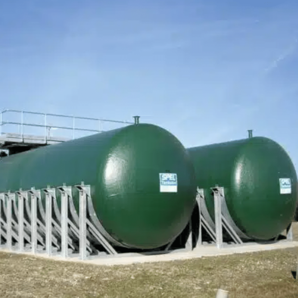
Tanks

Tanks

SPEL TankstorĀ® tanks have been developed with 60 years of experience in the market of underground GRP tanks.

In 1989 SPEL developed the technically advanced chop-hoop filament winding process to provide the most structurally sound and economic solution. This was patented in 1989 and further improved to include above and below ground fluid storage and treatment. The current range of tanks is available in five diameters 1.2, 1.8, 2.6, 3.5 and 4m internal dia.

Designed to the well-recognised British Standard BS EN 13121 they carry The SPEL 25 Year Shell Warranty and have a life expectancy of over 50 years.

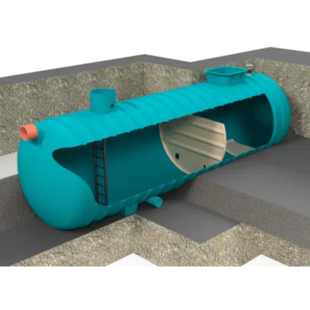
SPEL are a bespoke manufacturer and TankstorĀ® tanks have many uses including storage, stormwater attenuation, fire sprinkler systems, spill containment, potable water and chemical spill tanks, as well as wastewater applications, contact our team for more detail.

Connections are available in a range of sizes and types to suit site drainage. Access shafts in a range of sizes, in circular, square or rectangular can be fitted to suit applications. Partitions (non-load bearing and load bearing) can be fitted to provide chambers and/or baffles. Please contact our team for your bespoke application.

The SPEL 5 Stage Laminate Construction

SPEL GRP chambers are built inline with the British Standard BS EN 13121, which incorporates the critical 5 Stage Laminate Construction process. This enables SPEL to offer the industry-leading SPEL 25 Year Warranty even in challenging ground conditions.

Quality Control

The manufacturing process is fully ISO9001 certified and is carefully monitored with a digital read out system. Chopping glass, winding glass, the resin-rich inner layer and main laminate resins are kept within specification parameters thus minimising wastage and ensuring structural integrity.

Quality control procedures require each tank to be carefully inspected and tested. Ultrasonic thickness readings, material content weights, and more are checked and recorded against the tank’s unique serial number. Additional periodic laminate testing is carried out by independent testing facilities including stress and strain analysis and also physical property tests to meet specific design criteria.

Process

SPEL underground tanks are manufactured by the chophoop filament winding process developed in the US and specifically designed for underground tanks by SPEL Products, Patent No. 2233384.

GRP laminate

Design and specification for SPEL underground tanks

The SPEL underground tanks have been designed with reference to BS EN 13121, BS EN 976-1, 978 and BS EN 858-1:2002.

The quality and strength of glass reinforced plastic (GRP) laminates depends upon the following factors:

• The design criteria, eg. chemical resistance, temperature, internal and/or external loading.
• The efficiency and consistency of the manufacturing process and the high level of control to maintain resin and reinforcements within strict design parameters.
• The laminate construction from resin-rich corrosion resistant internal surface, resin-rich glass reinforced corrosion barrier, main laminate and the external resin-rich water penetration barrier providing excellent corrosion resistance from internal contents and complete sealing of laminate from ingress of water and/or contaminants externally.

Prior to determining the laminate construction and thickness using requirements, actual specimens are taken from filament wound laminates and independently tested. From the ongoing material tests and consideration of the various partial influence factors, which include the chemical resistance and a tank shell life to be excess of 25 years, a generous final design factor is determined.

The design of GRP laminates is clearly different from, for example, a steel structure where the material and loadings are clearly defined.

Tank manufacturers can cut their quality and price depending on the design factor determined.

SPEL underground tank laminates are designed to meet specific requirements, for example, hydrostatic load on tanks surrounded either in concrete or a free flowing pea
gravel.

With experience gained in the United States, high quality underground tanks do not suffer from degradation to the degree envisaged in the British Standard, in fact tests carried out on laminates taken from underground tanks in the US after 25 years use, have shown very little loss of strength.

The important factors are the construction and composition of the laminate to resist the corrosive action of the internal chemicals and the water or contaminated underground water externally.

BS EN 978 – Tests to this Standard determine the alpha and beta, ā€˜the long term deterioration due to creep and the effects of water or chemicals on the plastics’. Tests have been carried out, on pieces of shell cut from the tank barrel, by an independent test laboratory. The results are used in the equations (BS EN 976-1) to determine the stability of underground GRP horizontal cylindrical tanks for the nonpressure storage of liquid petroleum based fuels.

Chemical resistance and long term degradation

Further independent tests have been carried out in accordance with BS EN 858-1:2002 Section 8.1.4 ā€˜Chemical resistance of internal surfaces’. The tests involve full immersion of three test specimens for 1000 hours in four solutions; de-mineralised water at 40°C, fuel oil at 23°C, unleaded fuel at 23°C, caustic solution at 40°C.

The requirement in Section 6.2.7.1.3. ā€˜Plastic materials’ (BS EN 858-1) is for the glass reinforced test specimens under test to retain 80% of their strength when compared with the control specimen. The results of tests for tensile strength and flexural modulus have shown very little reduction, if any, in performance. In each case there was a reduction in flexural strength but an increase in modulus. Initially this might seem odd but it is possible that this could be part explained by at least two samples being immersed at 40°C hence a post cure compared to the control. All samples appeared to have passed seeing they came within the 80% retention of the control specimen.

Workshop conditions, Health & Safety and Environmental considerations.

Included in process controls is work shop temperature, fume extraction to keep within Health & Safety occupational exposure limits and odour control to meet the strict Environmental Protection Act 1990 Part 1 requirements as dictated by the Local Authority ā€˜Authorisation’ requirements. The record maintained since 1989, when the chop-hoop filament winding process was introduced, is that no tank has failed due to a design or manufacturing fault. Since 1989 thousands of underground tanks have been manufactured. The few tanks damaged were due to faulty installation or handling.

With this exceptional track record we are fully satisfied and confident that we have a specification and process control that produces exceptionally high quality laminates that have a life expectancy well in excess of 50 years.

The SPEL underground tank shell carries a 25 year warranty.

SPEL Laminate Construction

A Competitor Laminate Construction

GP – General purpose applications

Constructed throughout with orthophalic polyester resin and glass reinforcement.

Applications – potable water, sewage, surface water and mild chemicals.

CR – Chemical resistant lined tanks

The smooth moulded resin-rich corrosion resistant internal surface and the resin-rich glass reinforced corrosion barrier are constructed from isophthalic polyester resin or terephthalic NPG polyester resin.

Applications – suitable for silage effluent, chemicals (acidic) and hydrocarbon materials.

HCR – Highly chemical resistant

Aggressive chemicals and/or high temperatures. The smooth moulded resin-rich corrosion resistant internal surface and the resin-rich glass reinforced corrosion barrier are constructed from vinyl ester resins dependent upon chemical resistance and/or high temperatures.

Applications – transformer oil dump tanks, highly aggressive chemical process or holding tanks, and accidental chemical spillage containment tanks.

Suffix CG – Contaminated ground conditions

The external resin-rich water penetration barrier can also be in chemical resistant or highly chemical resistant where tanks are to be installed in contaminated ground.

Laminate construction to BS4994

SPEL TankstorĀ® underground tanks and separator shells are chop-hoop filament wound in quality glass reinforced plastics in accordance with the British Standard BS EN 13121.

To ensure a life expectancy in excess of 50 years underground and containing contaminated water or chemicals, the laminate construction must incorporate a chemical or corrosion barrier as defined in: Section two (BS EN 13121) 7. Construction of chemical barrier

7.3 Where a thermoset lining is used, in order to achieve the optimum properties, the construction of the laminate in contact with the corrodent shall consist of the following:

(a) Surface layer

A resin-rich surface layer reinforced with C glass surfacing mat, synthetic fibres or other suitable material, with a thickness between 0.25mm and 0.50mm.

(b) Backing layer

A backing layer normally containing a minimum of 1.2kg/m2 chopped glass strand or CSM with a soluble binder with between 25% and 33% glass content, by mass.

For tanks and vessels which are constructed in accordance with categories II and III, it is permissible to reduce the backing layer to 0.6kg/m2 chopped glass strand or CSM if agreed between the purchaser and the manufacturer.

Chop-hoop Filament Wound Shells

SPEL Laminate Construction

A Competitor Laminate Construction

This is the SPEL Puraceptor single chamber model sizing chart. For the difference between single and two chamber models see the explanation below under operation.

Model
Series
Nominal Size (NS)
Catchment Area (m2)
Oil Storage (L)
Silt Capacity (L)
Overall Length* (mm)
Overall Diameter (mm)
Inlet Invert (mm)
Base to Inlet (mm)
Base to Outlet (mm)
Optimum In/Out Pipe Diameter** (mm)
Number of Access Shafts(dia. mm)


Flow (l/s)


L

A
B
C

450
600
750
900
1200
P004 1C/SC
200
4
222
40
400
1,720
1,225
630
1,110
1,050
160
–
–
1
–
–
P006 1C/SC
200
6
333
60
600
2,310
1,225
630
1,110
1,050
160
–
–
1
–
–
P010 1C/SC
200
10
556
100
1,000
3,410
1,225
630
1,110
1,050
160
–
–
1
–
–
P015 1C/SC
300
15
833
150
1,500
3,200
1,875
350
1,800
1,740
225
1
–
1
–
–
P020 1C/SC
300
20
1,111
200
2,000
3,540
1,875
350
1,800
1,740
225
–
1
1
–
–
FP 1C/SC
300
20
1,111
200
2,000
4,290
1,875
350
1,800
1,740
225
–

1
–
–
P030 1C/SC
300
30
1,667
300
3,000
4,420
1,875
390
1,760
1,700
300
–
1
–
1
–
P040 1C/SC
300
40
2,222
400
4,000
5,760
1,875
390
1,760
1,700
300
–
1
–
1
–
P050 1C/SC
300
50
2,778
500
5,000
7,060
1,875
390
1,760
1,700
300
–
1
–
1
–
P065 1C/SC
400
65
3,611
650
6,500
4,860
2,700
425
2,625
2,525
300
–
1
–
2
–
P080 1C/SC
400
80
4,444
800
8,000
5,700
2,700
425
2,625
2,525
300
–
1
–
2
–
P100 1C/SC
400
100
5,555
1,000
10,000
7,400
2,700
475
2,575
2,475
450
–
1
–
2
–
P125 1C/SC
400
125
6,944
1,250
12,500
8,580
2,700
475
2,575
2,475
450
–
–
1
2
–
P150 1C/SC
400
150
8,333
1,500
15,000
10,180
2,700
475
2,575
2,475
450
–
–
1
2
–
P165 1C/SC
400
165
9,166
1,650
16,500
11,200
2,700
500
2,550
2,450
450
–
2
1
1
–
P200 1C/SC
400
200
11,110
2,000
20,000
13,710
2,700
660
2,390
2,290
600
–
2
1
1
–
P250 1C/SC
400
250
13,888
2,500
25,000
16,750
2,700
660
2,390
2,290
600
–
2
1
2
–
P280 1C/SC
400
280
15,555
2,800
28,000
18,800
2,700
660
2,390
2,290
600
–
1
2
2
–
P300 1C/SC
500
300
16,665
3,000
30,000
12,410
3,650
805
3,070
2,970
750
–
1
2
2
–
P400 1C/SC
500
400
22,220
4,000
40,000
15,760
3,650
805
3,070
2,970
750
–
2
2
2
–
P500 1C/SC
500
500
27,775
5,000
50,000
20,530
3,650
955
2,920
2,820
900
–
2
2
1
1
P500 1C/SC
600
500
27,775
5,000
50,000
16,040
4,150
925
3,250
3,150
900
–
2
2
1
1
P600 1C/SC
600
600
33,330
6,000
60,000
19,080
4,150
925
3,250
3,150
900
–
2
2
–
2
P700 1C/SC
600
700
38,888
7,000
70,000
21,460
4,150
925
3,250
3,150
900
–
3
2
3
–
P800 1C/SC
600
800
44,440
8,000
80,000
23,020
4,150
925
3,250
3,150
900
–
3
2
2
1
All of the above models are available without silt capacity, below are selected models for size comparison. The P1000 model is only available in non silt format.
P050 1C
300
50
2,778
500
–
5,070
1875
390
1,760
1,700
300
–
–
–
1
–
P065 1C
400
65
3,611
650
–
3,710
2,700
425
2,625
2,525
300
–

–
2
–
P100 1C
400
100
5,555
1,000
–
5,250
2,700
475
2,575
2,475
450
–

–
2
–
P125 1C
400
125
6,944
1,250
–
6,090
2,700
475
2,575
2,475
450
–
–
–
2
–
P165 1C
400
165
9,166
1,650
–
7,960
2,700
500
2,550
2,450
450
–
2

1
–
P250 1C
400
250
13,888
2,500
–
11,830
2,700
660
2,390
2,290
600
–
2

2
–
P300 1C
400
300
16,665
3,000
–
14,120
2,700
660
2,390
2,290
600
–
2

2
–
P500 1C
500
500
27,775
5,000
–
14,340
3,650
955
2,920
2,820
900
–
2
2
1
1
P500 1C
600
500
27,775
5,000
–
11,470
4,150
925
3,250
3,150
900
–
2
2
1
1
P700 1C
600
700
38,888
7,000
–
15,880
4,150
925
3,250
3,150
900
–
3
2
3
–
P1000 1C
600
1,000
55,550
10,000
–
21,407
4,150
925
3,250
3,150
900
–
3
2
1
3

*Overall length subject to inlet/outlet and orientation.

**SPEL Separators are designed for a maximum flow (NS/NSB) but can be fitted with larger than the recommended maximum connection size IN/OUT or with the addition of adapters providing the maximum flow (NS/NSB) cannot be exceeded or any increase in the operating level in the SPEL Separator to cause the captured pollutants to escape into the vent connections or through access shaft connections. Any overriding of the above criteria could jeopardise performance to the European Standard BS EN 858-1.

Note: Model FP1C/SC is a special Forecourt separator with 7600 litre spillage holding capacity. Click here for more information on Forecourt Separators.

This is the SPEL Puraceptor two chamber model sizing chart. For the difference between single and two chamber models see the explanation below under operation.

Model
Series
Nominal Size (NS)
Catchment Area (m2)
Oil Storage (L)
Silt Capacity (L)
Overall Length* (mm)
Overall Diameter (mm)
Inlet Invert (mm)
Base to Inlet (mm)
Base to Outlet (mm)
Optimum In/Out Pipe Diameter** (mm)
Number of Access Shafts(dia. mm)


Flow (l/s)


L

A
B
C

450
600
750
900
1200
P006 2C/SC
200
6
333
60
600
3,050
1,225
340
1,200
1,140
160
–
1
1
–
–
P010 2C/SC
200
10
556
100
1,000
4,690
1,225
340
1,200
1,140
160
–
1
1
–
–
P015 2C/SC
300
15
833
150
1,500
4,015
1,875
350
1,800
1,740
225
–
–
2
–
–
P020 2C/SC
300
20
1,111
200
2,000
4,015
1,875
350
1,800
1,740
225
–
–
2
–
–
FP 2C/SC***
300
20
1,111
200
2,000
5,500
1,875
350
1,800
1,740
225
–
–
2
–
–
P025 2C/SC
300
25
1,389
250
2,500
4,290
1,875
350
1,800
1,740
225
–
–
2
–
–
P030 2C/SC
300
30
1,667
300
3,000
4,420
1,875
390
1,760
1,700
300
–
1
2
–
–
P035 2C/SC
300
35
1,944
350
3,500
5,070
1,875
390
1,760
1,700
300
–
1
2
–
–
P040 2C/SC
300
40
2,222
400
4,000
5,760
1,875
390
1,760
1,700
300
–
1
2
–
–
P050 2C/SC
300
50
2,778
500
5,000
7,060
1,875
390
1,760
1,700
300
–
1
2
–
–
P065 2C/SC
300
65
3,611
650
6,500
9,180
1,875
390
1,760
1,700
300
1
–
2
–
–
P080 2C/SC
400
80
4,444
800
8,000
5,700
2,700
425
2,625
2,525
300
–
–
1
1
–
P100 2C/SC
400
100
5,555
1,000
10,000
7,400
2,700
475
2,575
2,475
450
–
–
1
1
–
P125 2C/SC
400
125
6,944
1,250
12,500
8,580
2,700
475
2,575
2,475
450
–
–
2
1
–
P150 2C/SC
400
150
8,333
1,500
15,000
10,180
2,700
500
2,550
2,450
450
–
–
2
1
–
P200 2C/SC
400
200
11,110
2,000
20,000
13,710
2,700
660
2,390
2,290
600
–
1
2
1
–
P250 2C/SC
400
250
13,888
2,500
25,000
16,752
2,700
660
2,390
2,290
600
–
2
1
2
–
P300 2C/SC
500
300
16,665
3,000
30,000
12,530
3,650
675
3,200
3,100
600
–
1
2
–
1
P400 2C/SC
500
400
22,220
4,000
40,000
15,980
3,650
675
3,200
3,100
600
–
2
2
2
–
P500 2C/SC
500
500
27,775
5,000
50,000
20,530
3,650
955
2,920
2,820
900
–
2
2
1
1
P500 2C/SC
600
500
27,775
5,000
50,000
16,260
4,150
925
3,250
3,150
900
–
2
1
1
1
P600 2C/SC
600
600
33,330
6,000
60,000
19,080
4,150
925
3,250
3,150
900
–
2
2
3
–
P700 2C/SC
600
700
38,888
7,000
70,000
22,270
4,150
925
3,250
3,150
900
–
3
2
3
–
P800 2C/SC
600
800
44,440
8,000
80,000
23,020
4,150
925
3,250
3,150
900
–
3
2
2
1
P900 2C/SC
600
900
50,000
9,000
90,000
24,658
4,150
925
3,250
3,150
900
–
3
2
1
2

*Overall length subject to inlet/outlet and orientation.

**SPEL Separators are designed for a maximum flow (NS/NSB) but can be fitted with larger than the recommended maximum connection size IN/OUT or with the addition of adapters providing the maximum flow (NS/NSB) cannot be exceeded or any increase in the operating level in the SPEL Separator to cause the captured pollutants to escape into the vent connections or through access shaft connections. Any overriding of the above criteria could jeopardise performance to the European Standard BS EN 858-1.

Note: Model FP2C/SC is a special Forecourt separator with 7600 litre spillage holding capacity. Click here for more information on Forecourt Separators.

[
ModelSeriesMeals per Day*NSGTank Length (mm)Internal Diameter (mm)Overall Capacity (L)Grease Capacity (L)Inlet Invert (m)Base to Inlet (mm)Base to Outlet(mm)Optimum In/Out Pipe Diameter** (mm)Number of Access Shafts (dia. mm)
LABC600
GS200/200020040042,0401,2002,0001601,0201,0009401602
GS200/300020060062,9301,2003,0002401,0201,0009401602
GS200/400020090093,8101,2004,0003601,0201,0009401602
GS200/50002001100114,7001,2005,0004401,0201,0009401602
GS200/60002001400145,5781,2006,0005601,0201,0009401602
GS300/58603001400142,6901,8005,8605601,6001,6001,5501602
GS300/92703001800184,0151,8009,2707201,6001,6001,5501602
GS300/182003004000407,6201,80018,20016001,6001,6001,5501602
ModelSeriesMax. Flow*Silt Capacity (L)Overall Length*Internal Diameter (mm)Opt In/Out Pipe Diameter (mm)Number of Access Shafts (dia. mm)Inlet Invert (mm)
Flow (l/s)L600A
WDS 200/10002001.12501.171,200160mm1–
WDS 200/20002002.25002.051,200160mm1–
WDS 200/30002003.37002.931,200160mm1–
WDS 200/40002004.51,0003.821,200160mm1–
WDS 200/50002005.61,2504.71,200160mm1–
WDS 200/60002006.71,5005.591,200160mm1–
WDS 200/70002007.81,7506.481,200160mm1–
WDS 200/800020092,0007.361,200160mm1–
WDS 200/9000200102,2508.251,200160mm1–
WDS 200/10,000200112,5009.131,200160mm1–
WDS 300/400030051,0001.951,800160mm1–
WDS 300/600030071,5002.761,800160mm1–
WDS 300/800030092,0003.541,800160mm1–
WDS 300/10,000300122,5004.291,800160mm1–
ModelSeriesNominal Size (NB)Catchment Area (M2)Oil Storage (L)Silt Capacity (L)Overall Length* (mm)Overall Diameter (mm)Inlet Invert (mm)Base to Inlet (mm)Base to Outlet (mm)Optimum In/Out pipe Diameter** (mm)Number of Access Shafts (dia. mm)
Flow (l/s)ABC450600750
FR004 SC2004222404001,72012256301,1101,0501601
FR006 SC2006333606002,2701,2256301,1101,0501601
FR010 SC200105561001,0003,4101,2256301,1101,0501601
FR015 SC300158331501,5002,7601,8753501,8001,7402251
FR020 SC300201,1112002,0003,2001,8753501,8001,7402251
FS2 SC300201,1112002,0004,2901,8753501,8001,7402251
FR030 SC300301,6673003,0004,4201,8753901,7601,7003001
FR040 SC300402,2224004,0005,7601,8753901,7601,7003001
FR050 SC300502,7785005,0007,0601,8753901,7601,7003001
FR065 SC400653,6116506,5004,8102,7004252,6252,52530011
FR080 SC400804,4448008,0005,7002,7004252,6252,52530011
FR100 SC4001005,5551,00010,0007,4002,7004752,5752,47545011
FR125 SC4001256,9441,25012,5008,5802,7004752,5752,47545011
FR150 SC4001508,3331,50015,00010,1802,7004752,5752,47545011
FR165 SC4001659,1661,65016,50011,2002,7005002,5502,4504502
FR200 SC40020011,1102,00020,00013,7102,7006602,3902,2906002
FR250 SC40025013,8882,50025,00016,7502,7006602,3902,2906002
ModelSeriesNominal Size (NB)Catchment Area (M2)Oil Storage (L)Silt Capacity (L)Overall Length* (mm)Overall Diameter (mm)Inlet Invert (mm)Base to Inlet (mm)Base to Outlet (mm)Optimum In/Out pipe Diameter** (mm)Number of Access Shafts (dia. mm)
Flow (l/s)ABC450600750
FR040300402,2224004,0201,8753901,7601,7003001
FR050300502,7785005,0701,8753901,7601,7003001
FR065400653,6116503,7102,7004252,6252,52530011
FR080400804,4448004,4002,7004252,6252,52530011
FR1004001005,55510005,2502,7004752,5752,47545011
FR1254001256,94412506,0902,7004752,5752,47545011
FRI504001508,33315007,4002,7004752,5752,47545011
FR1654001659,16616507,9602,7005002,5502,4504502
FR20040020011,11020009,6002,7006602,3902,2906002
FR25040025013,888250011,8302,7006602,3902,2906002
FR30040030016,665300014,1202,7006602,3902,2906002
FR400500400222,2224,000optional*3,650–3–

*Overall length subject to inlet/outlet size and orientation

**SPEL Separators are designed for a maximum flow (NS/NSB) but can be fitted with larger than the recommended maximum connection size IN/OUT or with the addition of adapters providing the maximum flow (NS/NSB) cannot be exceeded or any increase in the operating level in the SPEL Separator to cause the captured pollutants to escape into the vent connections or through access shaft connections. Any overriding of the above criteria could jeopardise performance to the European Standard BS EN 858-1.

Note: Model FS2SC is a special forecourt unit with 7600 litre spillage holding capacity.

Model
Series
Nominal Size (NS)
Catchment Area (m2)
Oil Storage (L)
Silt Capacity (L)
Overall Length (mm)
Inlet Invert (mm)
Base to Inlet (mm)
Base to Outlet (mm)
Optimum Inlet dia.** (mm)


Flow (l/s)


L


P006 2C/SC/M
300
6
333
60
600
3,200
640
1,610
1,550
160
P010 2C/SC/M
300
10
556
100
1000
5,070
540
1,610
1,550
160
P020 2C/SC/M
400
20
1,111
200
2000
5,250
625
2,425
2,325
225
P025 2C/SC/M
400
25
1,389
250
2500
6,170
625
2,425
2,325
225
P030 2C/SC/M
400
30
1,667
300
3000
7,400
625
2,425
2,325
300
P040 2C/SC/M
400
40
2,222
400
4000
9,930
For details, please contact our Technical Sales Team
300
P060 2C/SC/M
400
60
3,333
600
6000
13,710
For details, please contact our Technical Sales Team

300
P080 2C/SC/M
500
80
4,444
800
8000
10,040
For details, please contact our Technical Sales Team

300
P100 2C/SC/M
500
100
5,555
1,000
10,000
12,530
For details, please contact our Technical Sales Team

450
ModelSeriesNominal Size (NS)Catchment Area (m2)Oil Storage (L)Silt Capacity (L)Overall Length* (mm)Overall Diameter (mm)Inlet Invert (mm)Base to Inlet (mm)Base to Outlet (mm)Optimum In/Out Pipe Diameter** (mm)Number of Access Shafts (dia. mm)
Flow (l/s)LABC4507509001200
P006 2C/SC/NG2006333606003,05012254271,1101,050160–11–
P010 2C/SC/NG200105561001,0004,7001,2254271,1101,050160–3––
P015 2C/SC/NG300158331501,5004,0201,8755401,6101,550225–3––
P020 2C/SC/NG300201,1112002,0004,0201,8755401,6101,550225–3––
P025 2C/SC/NG300251,3892502,5004,2901,8755401,6101,550225–3––
P030 2C/SC/NG300301,6673003,0005,0701,8755501,6001,500300–21–
P040 2C/SC/NG300402,2224004,0006,5701,8755501,6001,500300–21–
P050 2C/SC/NG300502,7785005,0008,2601,8755501,6001,500300–21–
P065 2C/SC/NG300653,6116506,50010,2201,8755501,6001,500300121–
P065 2C/SC/NG400653,6116506,5005,4702,7006652,3852,285300111–
P080 2C/SC/NG400804,4448008,0006,1702,7006652,3852,285300111–
P100 1C/SC/NG4001005,5551,00010,00074002,70066523852285450111–
P125 2C/SC/NG4001256,9441,25012,5009,6002,7007652,2852,18545012–1
P150 2C/SC/NG4001508,3331,50015,00011,2002,7007902,2802,18045012–1
P200 2C/SC/NG40020011,1102,00020,00016,4002,7009402,1302,03060022–1
P300 2C/SC/NG50030016,6653,00030,00012,5303,6508753,0002,90060022–1
P400 2C/SC/NG50040022,2204,00040,00016,3303,6508753,0002,900600322–
ModelSeriesNominal Size (NS)Catchment Area (m2)Oil Storage (L)Silt Capacity (L)Overall Length* (mm)Overall Diameter (mm)Inlet Invert (mm)Base to Inlet (mm)Base to Outlet (mm)Optimum In/Out Pipe Diameter* (mm)Number of Access Shafts (dia. mm)
Flow (l/s)LABC7509001200
FP 1C/SCClass 1 Forecourt SeparatorSingle Chamber with Silt Capture300201,1112002,0004,2901,8753501,8001,7402251––
FP 2C/SCClass 1 Forecourt SeparatorTwo Chamber with Silt Capture300201,1112002,0005,5001,8753501,8001,7402252––
FS2 SCClass 2 Forecourt SeparatorSingle Chamber with Silt Capture300201,1112002,0004,2901,8753501,8001,740225––1
Model
Series
Nominal Size (NS)
Catchment Area (m2)
Oil Storage (L)
Silt Capacity (L)
Overall Length* (mm)
Overall Diameter (mm)
Inlet Invert (mm)
Base to Inlet (mm)
Base to Outlet (mm)
Optimum In/Out Pipe Diameter** (mm)
Number of Access Shafts(dia. mm)


Flow (l/s)


L

A
B
C

450
600
750
900
1200
P006 2C/SC
200
6
333
60
600
3,050
1,225
340
1,200
1,140
160
–
1
1
–
–
P010 2C/SC
200
10
556
100
1,000
4,690
1,225
340
1,200
1,140
160
–
1
1
–
–
P015 2C/SC
300
15
833
150
1,500
4,015
1,875
350
1,800
1,740
225
–
–
2
–
–
P020 2C/SC
300
20
1,111
200
2,000
4,015
1,875
350
1,800
1,740
225
–
–
2
–
–
FP 2C/SC***
300
20
1,111
200
2,000
5,500
1,875
350
1,800
1,740
225
–
–
2
–
–
P025 2C/SC
300
25
1,389
250
2,500
4,290
1,875
350
1,800
1,740
225
–
–
2
–
–
P030 2C/SC
300
30
1,667
300
3,000
4,420
1,875
390
1,760
1,700
300
–
1
2
–
–
P035 2C/SC
300
35
1,944
350
3,500
5,070
1,875
390
1,760
1,700
300
–
1
2
–
–
P040 2C/SC
300
40
2,222
400
4,000
5,760
1,875
390
1,760
1,700
300
–
1
2
–
–
P050 2C/SC
300
50
2,778
500
5,000
7,060
1,875
390
1,760
1,700
300
–
1
2
–
–
P065 2C/SC
300
65
3,611
650
6,500
9,180
1,875
390
1,760
1,700
300
1
–
2
–
–
P080 2C/SC
400
80
4,444
800
8,000
5,700
2,700
425
2,625
2,525
300
–
–
1
1
–
P100 2C/SC
400
100
5,555
1,000
10,000
7,400
2,700
475
2,575
2,475
450
–
–
1
1
–
P125 2C/SC
400
125
6,944
1,250
12,500
8,580
2,700
475
2,575
2,475
450
–
–
2
1
–
P150 2C/SC
400
150
8,333
1,500
15,000
10,180
2,700
500
2,550
2,450
450
–
–
2
1
–
P200 2C/SC
400
200
11,110
2,000
20,000
13,710
2,700
660
2,390
2,290
600
–
1
2
1
–
P250 2C/SC
400
250
13,888
2,500
25,000
16,752
2,700
660
2,390
2,290
600
–
2
1
2
–
P300 2C/SC
500
300
16,665
3,000
30,000
12,530
3,650
675
3,200
3,100
600
–
1
2
–
1
P400 2C/SC
500
400
22,220
4,000
40,000
15,980
3,650
675
3,200
3,100
600
–
2
2
2
–
P500 2C/SC
500
500
27,775
5,000
50,000
20,530
3,650
955
2,920
2,820
900
–
2
2
1
1
P500 2C/SC
600
500
27,775
5,000
50,000
16,260
4,150
925
3,250
3,150
900
–
2
1
1
1
P600 2C/SC
600
600
33,330
6,000
60,000
19,080
4,150
925
3,250
3,150
900
–
2
2
3
–
P700 2C/SC
600
700
38,888
7,000
70,000
22,270
4,150
925
3,250
3,150
900
–
3
2
3
–
P800 2C/SC
600
800
44,440
8,000
80,000
23,020
4,150
925
3,250
3,150
900
–
3
2
2
1
P900 2C/SC
600
900
50,000
9,000
90,000
24,658
4,150
925
3,250
3,150
900
–
3
2
1
2
Model
Series
Nominal Size (NS)
Catchment Area (m2)
Oil Storage (L)
Silt Capacity (L)
Overall Length* (mm)
Overall Diameter (mm)
Inlet Invert (mm)
Base to Inlet (mm)
Base to Outlet (mm)
Optimum In/Out Pipe Diameter** (mm)
Number of Access Shafts(dia. mm)


Flow (l/s)


L

A
B
C

450
600
750
900
1200
P004 1C/SC
200
4
222
40
400
1,720
1,225
630
1,110
1,050
160
–
–
1
–
–
P006 1C/SC
200
6
333
60
600
2,310
1,225
630
1,110
1,050
160
–
–
1
–
–
P010 1C/SC
200
10
556
100
1,000
3,410
1,225
630
1,110
1,050
160
–
–
1
–
–
P015 1C/SC
300
15
833
150
1,500
3,200
1,875
350
1,800
1,740
225
1
–
1
–
–
P020 1C/SC
300
20
1,111
200
2,000
3,540
1,875
350
1,800
1,740
225
–
1
1
–
–
FP 1C/SC
300
20
1,111
200
2,000
4,290
1,875
350
1,800
1,740
225
–

1
–
–
P030 1C/SC
300
30
1,667
300
3,000
4,420
1,875
390
1,760
1,700
300
–
1
–
1
–
P040 1C/SC
300
40
2,222
400
4,000
5,760
1,875
390
1,760
1,700
300
–
1
–
1
–
P050 1C/SC
300
50
2,778
500
5,000
7,060
1,875
390
1,760
1,700
300
–
1
–
1
–
P065 1C/SC
400
65
3,611
650
6,500
4,860
2,700
425
2,625
2,525
300
–
1
–
2
–
P080 1C/SC
400
80
4,444
800
8,000
5,700
2,700
425
2,625
2,525
300
–
1
–
2
–
P100 1C/SC
400
100
5,555
1,000
10,000
7,400
2,700
475
2,575
2,475
450
–
1
–
2
–
P125 1C/SC
400
125
6,944
1,250
12,500
8,580
2,700
475
2,575
2,475
450
–
–
1
2
–
P150 1C/SC
400
150
8,333
1,500
15,000
10,180
2,700
475
2,575
2,475
450
–
–
1
2
–
P165 1C/SC
400
165
9,166
1,650
16,500
11,200
2,700
500
2,550
2,450
450
–
2
1
1
–
P200 1C/SC
400
200
11,110
2,000
20,000
13,710
2,700
660
2,390
2,290
600
–
2
1
1
–
P250 1C/SC
400
250
13,888
2,500
25,000
16,750
2,700
660
2,390
2,290
600
–
2
1
2
–
P280 1C/SC
400
280
15,555
2,800
28,000
18,800
2,700
660
2,390
2,290
600
–
1
2
2
–
P300 1C/SC
500
300
16,665
3,000
30,000
12,410
3,650
805
3,070
2,970
750
–
1
2
2
–
P400 1C/SC
500
400
22,220
4,000
40,000
15,760
3,650
805
3,070
2,970
750
–
2
2
2
–
P500 1C/SC
500
500
27,775
5,000
50,000
20,530
3,650
955
2,920
2,820
900
–
2
2
1
1
P500 1C/SC
600
500
27,775
5,000
50,000
16,040
4,150
925
3,250
3,150
900
–
2
2
1
1
P600 1C/SC
600
600
33,330
6,000
60,000
19,080
4,150
925
3,250
3,150
900
–
2
2
–
2
P700 1C/SC
600
700
38,888
7,000
70,000
21,460
4,150
925
3,250
3,150
900
–
3
2
3
–
P800 1C/SC
600
800
44,440
8,000
80,000
23,020
4,150
925
3,250
3,150
900
–
3
2
2
1
All of the above models are available without silt capacity, below are selected models for size comparison. The P1000 model is only available in non silt format.
P050 1C
300
50
2,778
500
–
5,070
1875
390
1,760
1,700
300
–
–
–
1
–
P065 1C
400
65
3,611
650
–
3,710
2,700
425
2,625
2,525
300
–

–
2
–
P100 1C
400
100
5,555
1,000
–
5,250
2,700
475
2,575
2,475
450
–

–
2
–
P125 1C
400
125
6,944
1,250
–
6,090
2,700
475
2,575
2,475
450
–
–
–
2
–
P165 1C
400
165
9,166
1,650
–
7,960
2,700
500
2,550
2,450
450
–
2

1
–
P250 1C
400
250
13,888
2,500
–
11,830
2,700
660
2,390
2,290
600
–
2

2
–
P300 1C
400
300
16,665
3,000
–
14,120
2,700
660
2,390
2,290
600
–
2

2
–
P500 1C
500
500
27,775
5,000
–
14,340
3,650
955
2,920
2,820
900
–
2
2
1
1
P500 1C
600
500
27,775
5,000
–
11,470
4,150
925
3,250
3,150
900
–
2
2
1
1
P700 1C
600
700
38,888
7,000
–
15,880
4,150
925
3,250
3,150
900
–
3
2
3
–
P1000 1C
600
1,000
55,550
10,000
–
21,407
4,150
925
3,250
3,150
900
–
3
2
1
3
ModelNominal Size (NSB)Peak Flow (l/s)Catchment Area (m2)Oil Storage (L)Silt Storage (L)Length (mm)Internal Diameter (mm)Inlet Invert (mm)Base to Inlet (mm)Base to Outlet (mm)Optimum in/out Pipe Diameter (mm) for Orientation*Number of Access Shafts A-C Diameter (mm)
Flow (l/s)NSB x 15NSB x 100LWABC750*900
103 C1/SC3301,667453001,5501,3005001,015965160––
204 C1/SC4402,222604001,8601,2005501,3501,3003001–
206 C1/SC6603,333906002,1201,2005501,3501,3003001–
208 C1/SC8804,4441208002,2701,2005501,3501,3003001–
210 C1/SC101005,5561501,0002,9201,2005501,3501,3003001–
212 C1/SC121206,6671801,2003,5701,2005601,3501,3003001–
215 C1/SC151508,3332251,5004,2371,2005601,3501,3003001–
320 C1/SC2020011,1113002,0003,2001,8007001,4501,350450––
325 C1/SC2525013,8893752,5003,5401,8007001,4501,350450––
330 C1/SC3030016,6674503,0004,4201,8007001,4501,35045011
340 C1/SC4040022,2226004,0005,7601,8007401,4101,3104501–
345 C1/SC4545025,0006754,5006,5701,8007401,4101,3104501–
350 C1/SC5050027,7787505,0007,0601,8007401,4101,3104501–
460 C1/SC6060033,3339006,0004,4002,6009502,1002,00060011
470 C1/SC7070038,8891,0507,0005,2502,6009502,1002,00060011
480 C1/SC8080044,4441,2008,0006,1702,6009502,1002,00060011
4100 C1/SC1001,00055,5561,50010,0007,4002,6001,1001,9501,85075011
4125 C1/SC1251,25069,4441,87512,5009,0502,6001,1001,9501,85075011
4150 C1/SC1501,50083,3332,25015,0009,9502,6001,1001,9501,850750–2
4160 C1/SC1601,60088,8892,40016,00011,8302,6001,2501,8001,70075012
5180 C1/SC1801,800100,0002,70018,0007,4703,5001,1852,6902,55090012
5200 C1/SC2002,000111,0003,00020,0008,5303,5001,1852,4252,3251,20012
5250 C1/SC2502,500139,0003,75025,00010,0403,5001,1852,4252,3251,20012
6300 C1/SC3003,000167,0004,50030,00010,3104,0001,3252,8502,6751,20012
6350 C1/SC3503,500194,0005,25035,00011,5004,0001,3252,8502,6751,20023
6400 C1/SC4004,000222,0006,00040,00012,6904,0001,3252,8502,6751,20023
6500 C1/SC5005,000278,0007,50050,00015,8704,0001,3252,8502,6751,20024
6600 C1/SC6006,000333,0009,00060,00018,2604,0001,3252,8502,6751,20014
6700 C1/SC7007,000389,00010,50070,00022,2504,0001,3252,8502,6751,20025
6500 C15005,00027.87,500Nil11,9104,1501,3252,8502,6751,20014
6600 C16006,00033.39,000Nil13,5104,1501,3252,8502,6751,20014
6700 C17007,00038.910,500Nil16,6504,1501,3252,8502,6751,20015
6800 C18008,00044.412,000Nil19,8904,1501,3252,8502,6751,20016
ModelSeriesTreated Flow Rate (l/s)Maximum Design Storm Flow (l/s)Catchment area* (m²)Head Loss Storm Flow (mm)Overall Diameter (mm)Overall Chamber Height (mm)Inlet to Base (mm)Inlet Invert (mm)Silt Capacity (L)Hydrocarbon Capacity (L)Pipe Size dia. (mm)Access Opening (mm)
SHV 200/30200301224,0001801,2252,6801,6001,080360220300Ƙ750
SHV 300/70300702809,3332551,8253,8002,4001,4001,200900450Ƙ900
SHV 400/20040020065026,6653502,7005,0003,3001,7003,4502,000600Ƙ1,200
SHV 500/40050040090053,3335003,5405,3903,0002,3905,0004,800750Ƙ1,200
ModelSeriesMax. Flow (l/s)Catchment Area Based on 65mm/hrOil Storage (L)Silt Capacity (L)Tank Length (mm)Internal Diameter (mm)Inlet Invert (mm)Base to Inlet (mm)Base to Outlet (mm)Optimum in/out Pipe Diameter* (mm)Number of Access Shafts (dia. mm)
ABC4506007509001,200
P004/1C/ESR2004222404001,7101,2206301,1101,050160––1––
P006/1C/ESR2006333606002,3101,2206301,1101,050160––1––
P010/1C/ESR200105561001,0003,4001,2206301,1101,050160––1––
P015/1C/ESR300158331501,5003,2001,8003501,8001,7402251–1––
P020/1C/ESR300201,1112002,0003,5401,8003501,8001,740225–11––
P030/1C/ESR300301,6673003,0004,4201,803901,7601,700300–1–1–
P040/1C/ESR300402,2224004,0005,7601,8003901,7601,700300–1–1–
P050/1C/ESR300502,7785005,0007,0601,8003901,7601,700300–1–1–
P065/1C/ESR400653,6116506,5004,8102,6004252,6252,525300–1–2–
P080/1C/ESR400804,4448008,0005,7002,6004252,6252,525300–1–2–
P100/1C/ESR4001005,5551,00010,0007,4002,6004752,5752,475450–1–2–
P125/1C/ESR4001256,9441,25012,5008,5802,6004752,5752,475450––12–
P150/1C/ESR4001508,3331,50015,00010,1802,6004752,5752,475450––12–
P165/1C/ESR4001659,1661,65016,50011,2002,6005002,5502,450450––12–
P200/1C/ESR40020011,1102,00020,00013,7102,6006602,3902,290600–121–
P250/1C/ESR40025013,8882,50025,00016,7502,6006602,3902,290600–122–
P280/1C/ESR40028015,5552,80028,00018,8002,6006602,3902,290600–122–
P300/1C/ESR50030016,6653,00030,00012,4103,5008053,0702,970750–122–
P400/1C/ESR50040022,2204,00040,00015,7603,5008053,0702,970750–222–
P500/1C/ESR50050027,7755,00050,00020,5303,5009552,9202,820900–2211
P500/1C/ESR60050027,7755,00050,00016,0404,0009253,2503,150900–2211
P600/1C/ESR60060033,3306,00060,00019,0804,0009253,2503,150900–22–2
P700/1C/ESR60070038,8887,00070,00021,4704,0009253,2503,150900–323–
P800/1C/ESR60080044,4408,00080,00023,0204,0009253,2503,150900–3221
P900/1C/ESR60090049,8469,00090,00024,6584,0009253,2503,150900–32–3
ModelSeriesTreated Flow RateMaximum FlowConnectible / Catchment area (m²)*Oil Storage (litres)Silt Capacity (litres)Tank Length (mm)Internal Diameter (mm)Inlet Invert (mm)Base to Inlet (mm)Base to Outlet (mm)Optimum in / out pipe diameter ** (mm)Number of Access Shafts A-C*** (dia. mm)
LABC7509001200
210C1/ESR200101001,3331501,0002,9201,2205501,3501,3003001––
212C1/ESR200121201,60018012003,5701,2205501,3501,3003001––
215C1/ESR200151502,0002251,5004,2371,2205501,3501,3003001––
320C1/ESR300202002,6653002,0003,2001,8007001,4501,350450–––
325C1/ESR300252503,3333752,5003,5351,8007001,4501,350450–––
330C1/ESR300303004,0004503,0004,4201,8007001,4501,35045011–
340C1/ESR300404005,3336004,0005,7601,8007401,4101,3104501––
345C1/ESR300454506,0006754,5006,5631,8007401,4101,3104501––
350/C1/ESR300505006,6657505,0007,0601,8007401,4101,3104501––
460C1/ESR400606008,0009006,0004,4002,6009502,1002,00060011–
470C1/ESR400707009,3331,0507,0005,2502,6009502,1002,00060011–
480C1/ESR4008080010,6651,2008,0006,1702,6009502,1002,00060011–
4100C1/ESR4001001,00013,3331,50010,0007,4002,6001,1001,9501,85075011–
4125C1/ESR4001251,25016,6651,87512,5009,0002,6001,1001,9501,85075011–
4150C1/ESR4001501,50020,0002,25015,0009,9302,6001,1001,9501,850750–2–
4160C1/ESR4001601,60021,3332,40016,00011,8302,6001,2501,9501,85075012–
5180C1/ESR5001801,80024,0002,70018,0007,4723,5001,1852,6902,55090012–
5200C1/ESR5002002,00026,6653,00020,0008,5303,5001,1852,5702,3551,20012–
5250C1/ESR5002502,50033,3333,75025,00010,0403,5001,1852,6902,3551,200
6300C1/ESR6003003,00040,0004,50030,00010,3104,0001,3252,8502,6751,20012–
6350C1/ESR6003503,50046,6655,25035,00011,5004,0001,3252,8502,6751,20023–
6400C1/ESR6004004,00053,3336,00040,00012,6904,0001,3252,8502,6751,20023–
6500C1/ESR6005005,00066,6657,50050,00015,8804,0001,3252,8502,6751,20024–
6600C1/ESR6006006,00080,0009,00060,00018,2564,0001,3252,8502,6751,20015
6700C1/ESR6007007,00093,33310,50070,00022,2504,0001,3252,8502,6751,200

Live Chat

Request a Quote

Fill out the form below with your details and any info you wish to be considered by our team and we will be in touch shortly.Ā 

jQuery(function ($) { // Delegate clicks from any Elementor button inside the tabs widget $(document).on('click', '#spel-tabs .switch-to-specs', function (e) { e.preventDefault(); const $title = $('#spel-tabs #specs'); // your tab TITLE button if ($title.length) { $title.trigger('click'); // lets Elementor open the "Specification Chart" tab $title[0].scrollIntoView({ behavior: 'smooth', block: 'start' }); } }); });jQuery(function ($) { $(document).on('click', '#spel-tabs .elementor-button, #spel-tabs .elementor-button-link', function (e) { const $btn = $(this); const $wrap = $btn.closest('.elementor-element'); const targetId = $btn.attr('data-target-title-id') || $wrap.attr('data-target-title-id'); if (!targetId) return; e.preventDefault(); const $title = $('#spel-tabs #' + CSS.escape(targetId)); if ($title.length) { $title.trigger('click'); $title[0].scrollIntoView({ behavior: 'smooth', block: 'start' }); } }); });